Product Guide
Set Up Station
Unpack your FieldKit and check you have all the necessary parts.
Download App
Download the FieldKit mobile app before proceeding.
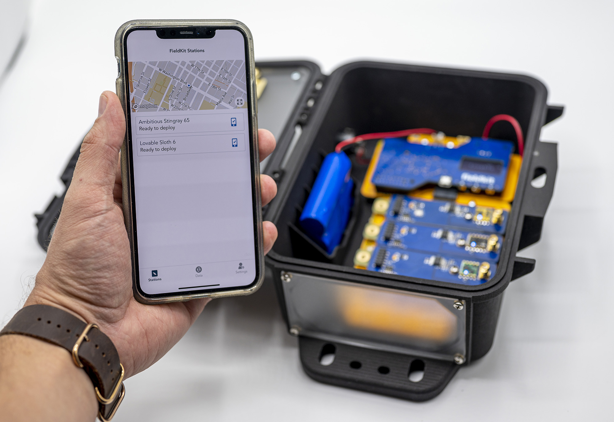
Download the FieldKit app from the iOS app store or Android app store onto your phone to guide your setup and view your data.

![]()
The app will help guide you through the entire setup and deployment process. While out in the field, you often won’t have internet access via WiFi. Using the mobile app gives you a direct connection to your FieldKit station via the Station WiFi (an access point created by the station).
If you haven’t done it yet, sign up for an account here at portal.fieldkit.org. That way, when you come to sync your station’s data to the web portal, you’ll be ready to go.
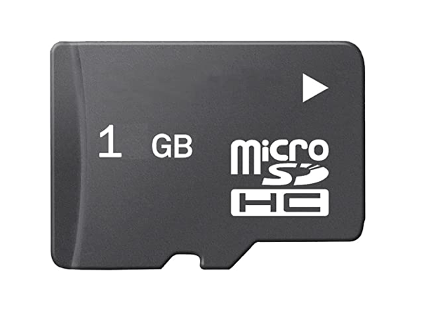
MicroSD card
We highly recommend using a microSD card in your station. This allows you to save a backup of your data and will keep all logs in case something goes wrong. You’ll also need one to update your firmware. We don’t sell these, but you should be able to pick one up pretty easily online or at a local retailer.
Calibration standardsSome sensors need to be calibrated to set a baseline for accurate readings and will also require periodic recalibration. We don’t sell calibration standards, but we can advise you on what you need to purchase. If you have not had your sensors pre-calibrated in our lab before shipment, you may want to go ahead and purchase calibration standards before assembling your kit, so you can be ready to go when you set up your station. Check out the Set Up Modules section for more details and feel free to reach out to our team with questions about your particular sensors.
Assemble Station
Carefully put together your FieldKit station.
1. Prepare to Assemble
Check that you have all necessary parts to assemble your FieldKit station. We strongly recommend going through the set-up of your station at home. This allows you to assemble your station fully, calibrate accurately, and connect to the internet for troubleshooting before you go into the field. Here’s a list of parts you’ll need to proceed (you can also see a list of parts with photos and helpful information at our FieldKit Parts List):
CORE
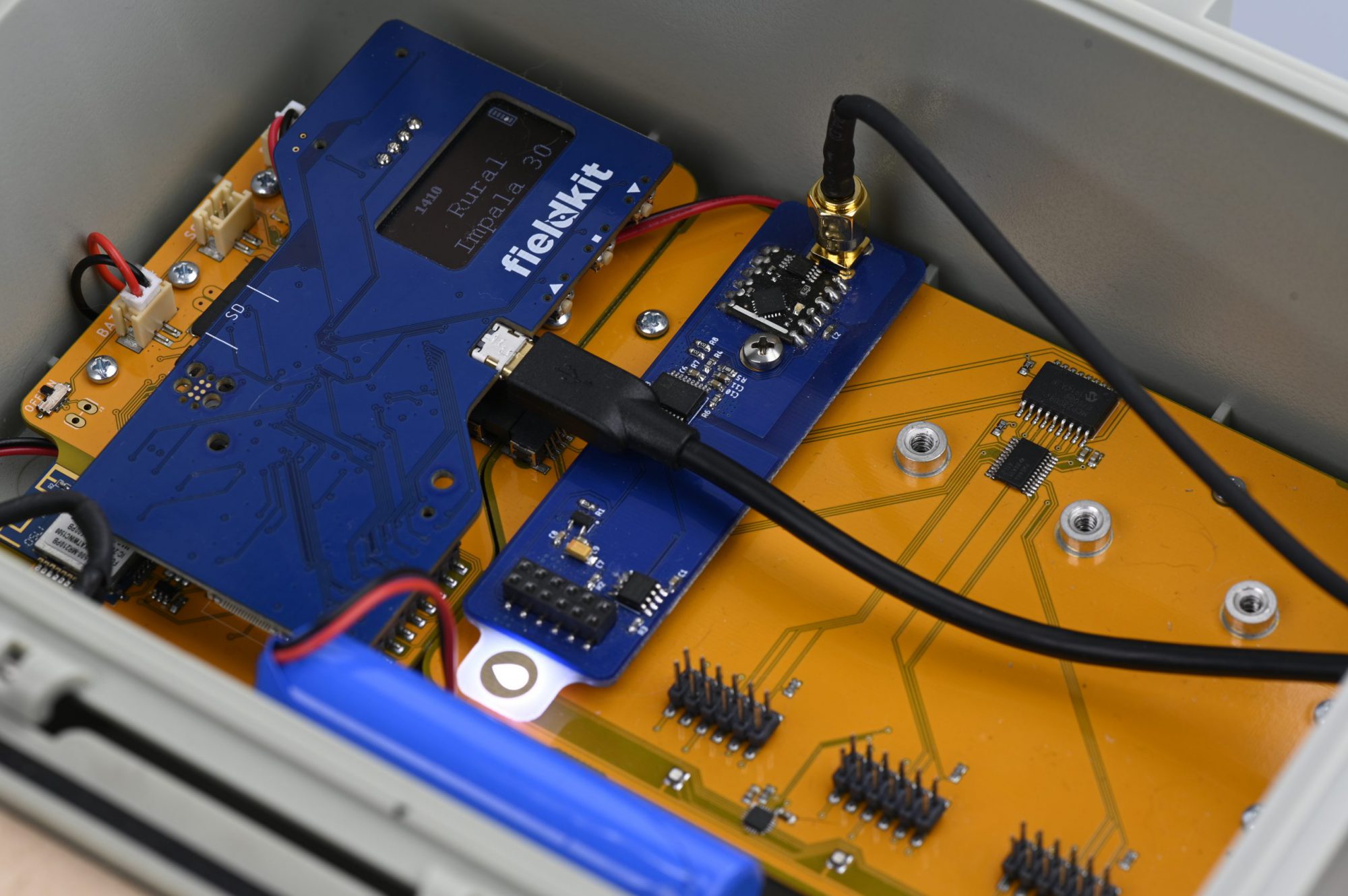
A) Upper Board
B) Lower Board
C) Module Base
SENSORS
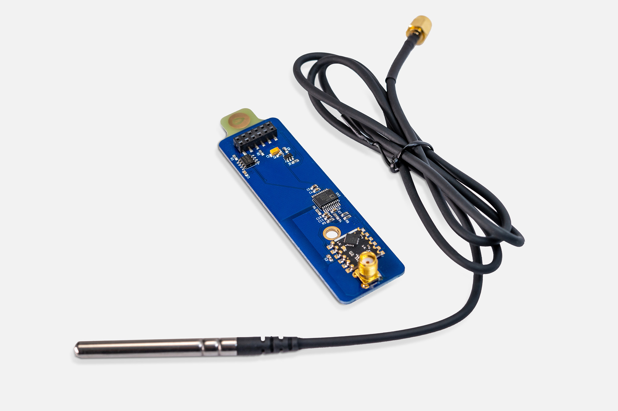
D) Module Board(s), found in each Sensor Pack
POWER
E) Battery
F) Micro-USB cable
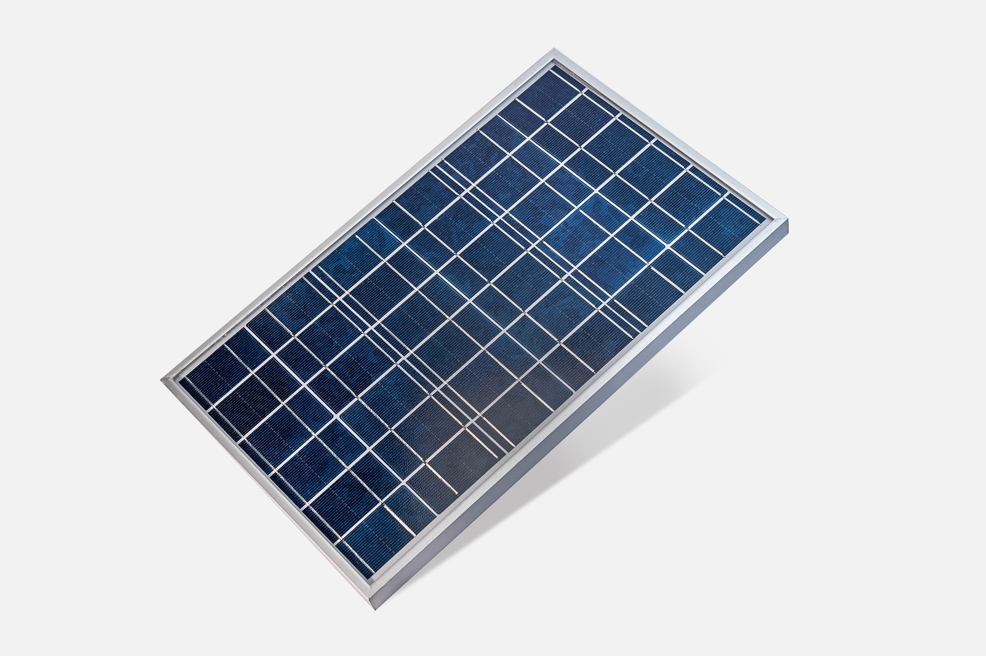
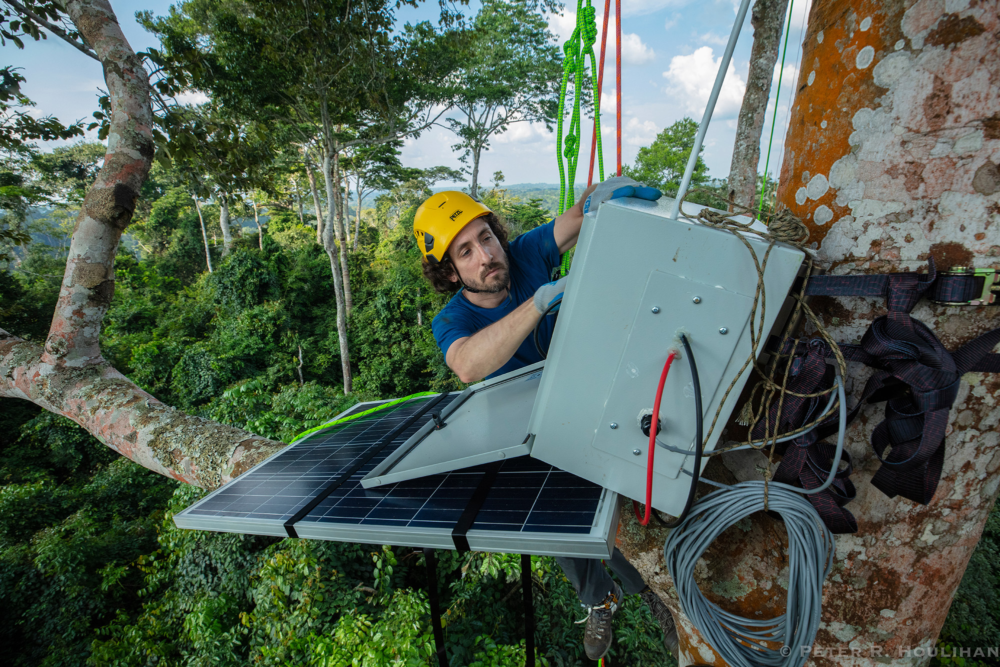
G) Solar Panel and Cable (optional)
CASE
H) FieldKit Case
I) Cable Plate Packs
J) Station Screw Packs
You will also need the following (not included):
–Phillips screwdriver*
–USB wall charger
*Some people prefer to use a small jeweler’s screwdriver while others are more comfortable with a regular sized screwdriver. Test out what works for you. Also, you might also like to have a small dish to hold the tiny screws.
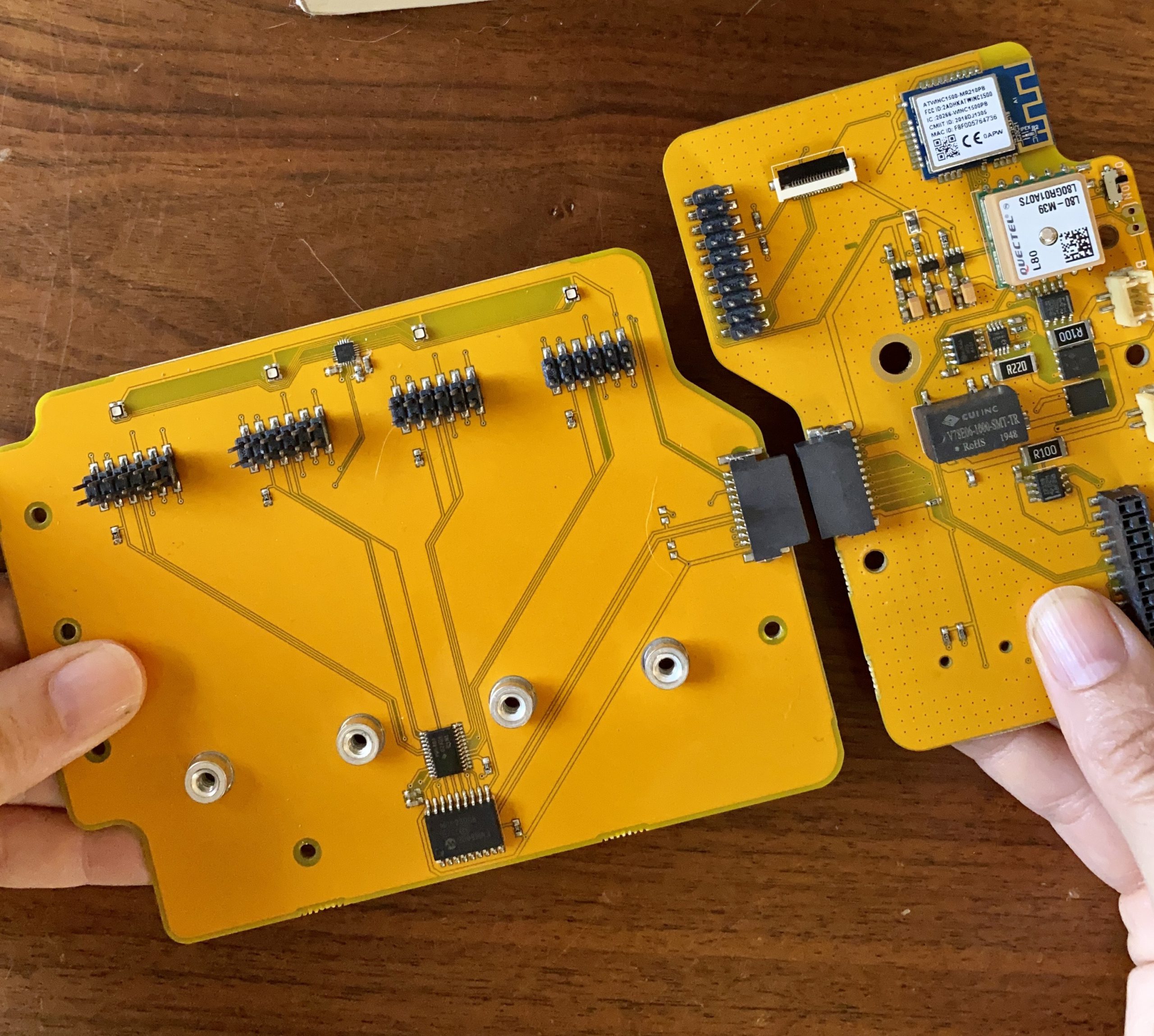
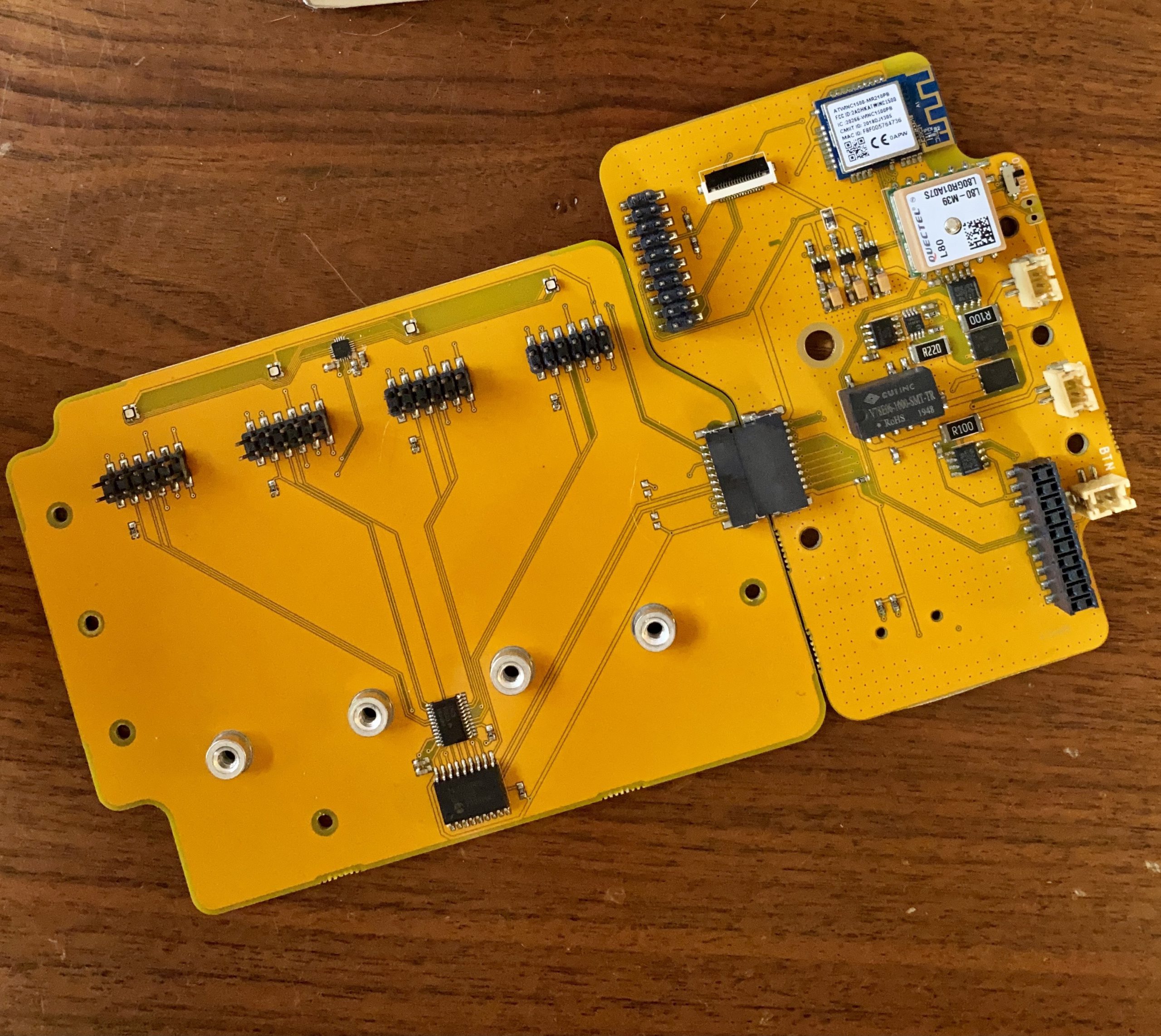
2. Separate the Upper and Lower Boards
The Upper and Lower Boards come pre-assembled to protect the pins, so you’ll need to pull them apart in order to secure the Lower Board to the case, before re-assembling them.
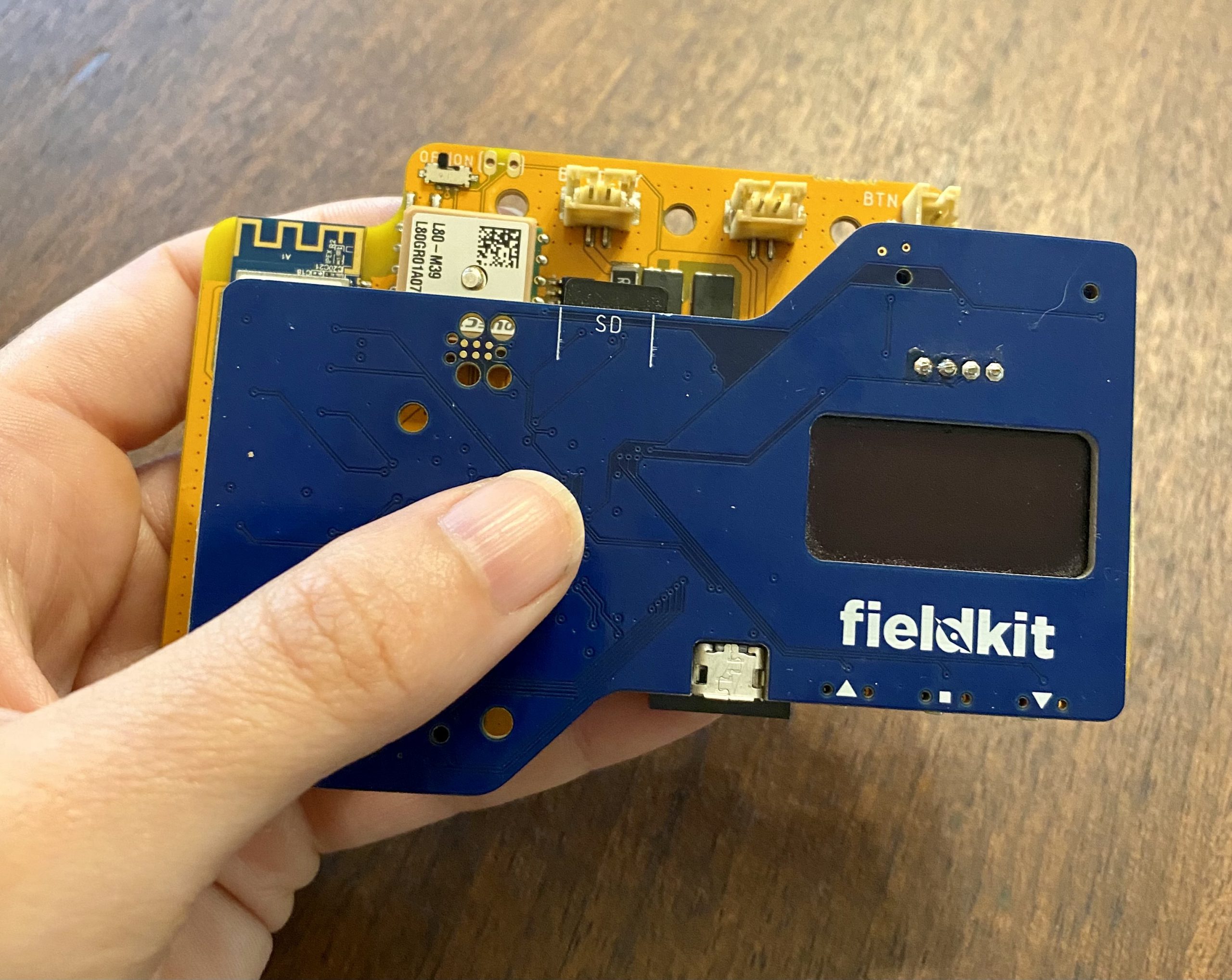
Take the Boards
Pick up the combined Upper and Lower Boards.
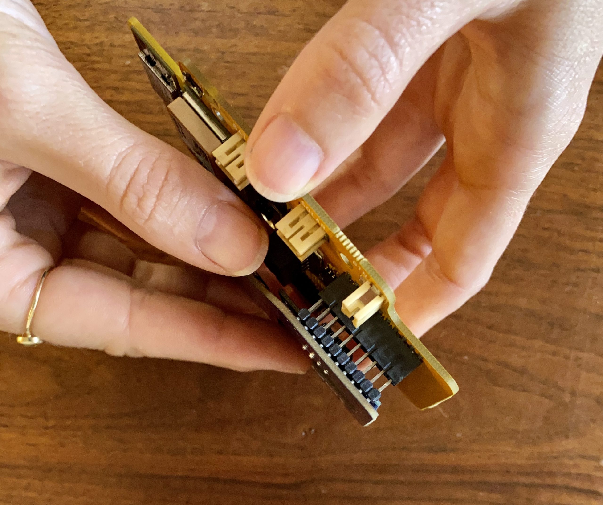
Pull Boards Apart
Hold the Upper Board between your thumb and forefinger, and the Lower Board similarly. Then, rock the boards back and forth gently on a diagonal plane to pull them apart. Set the Upper Board aside for now.
3. Attach Module Base
Attach the Lower Board to the Module Base.
Line Up
Line up the Lower Board with the Module Base.
Press Together
Press together. You’re now ready to start securing your boards in the case.
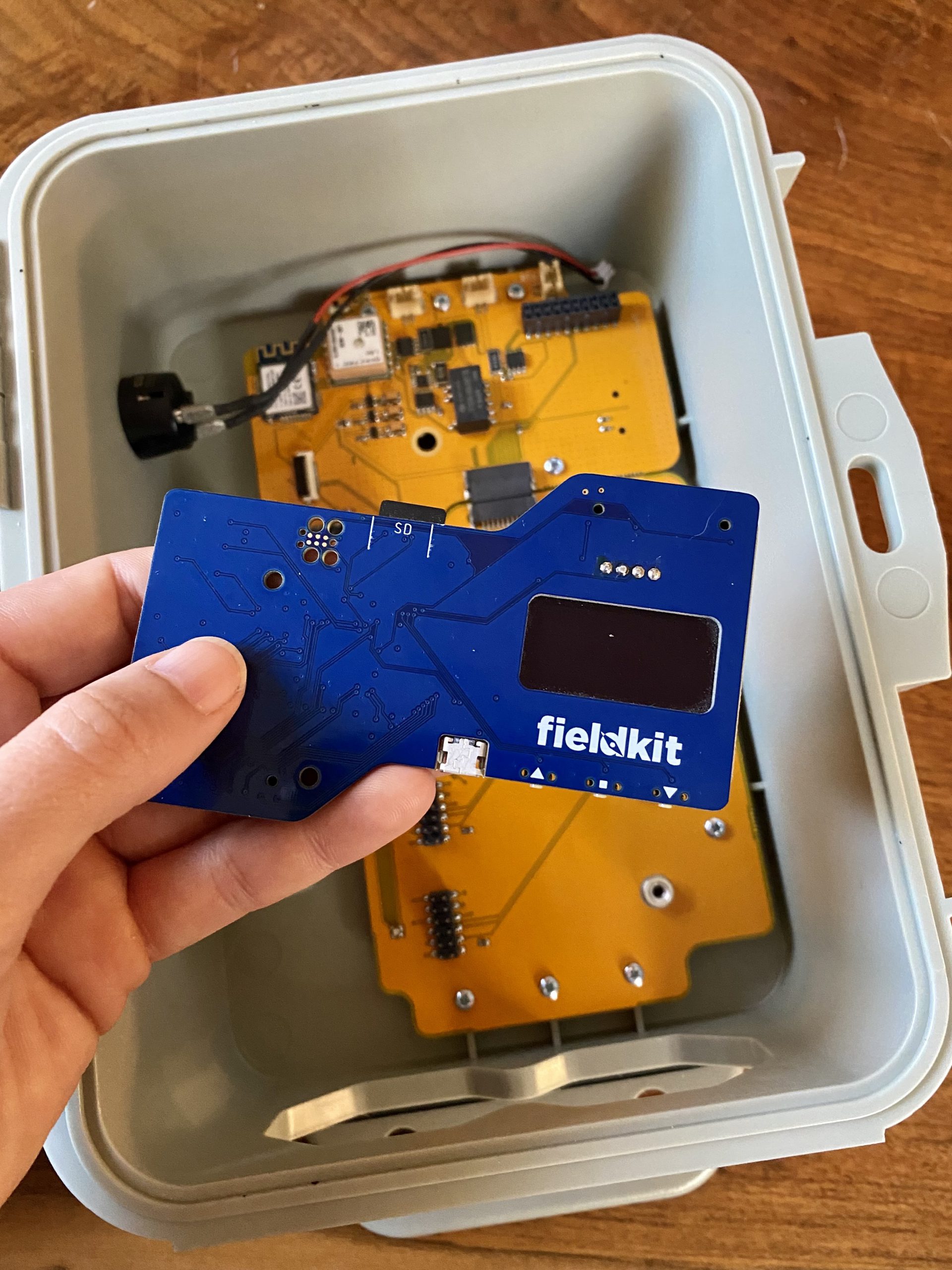
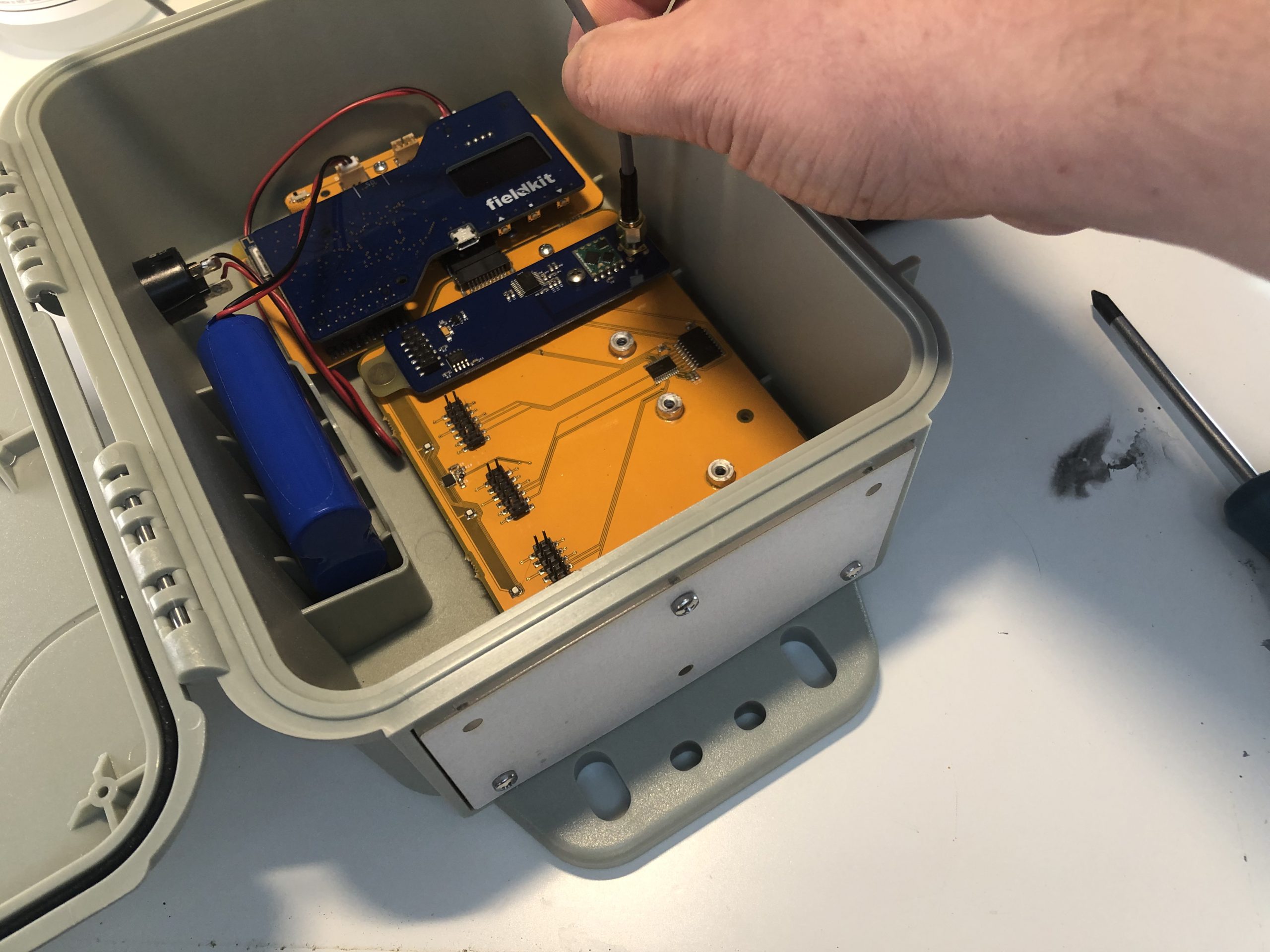
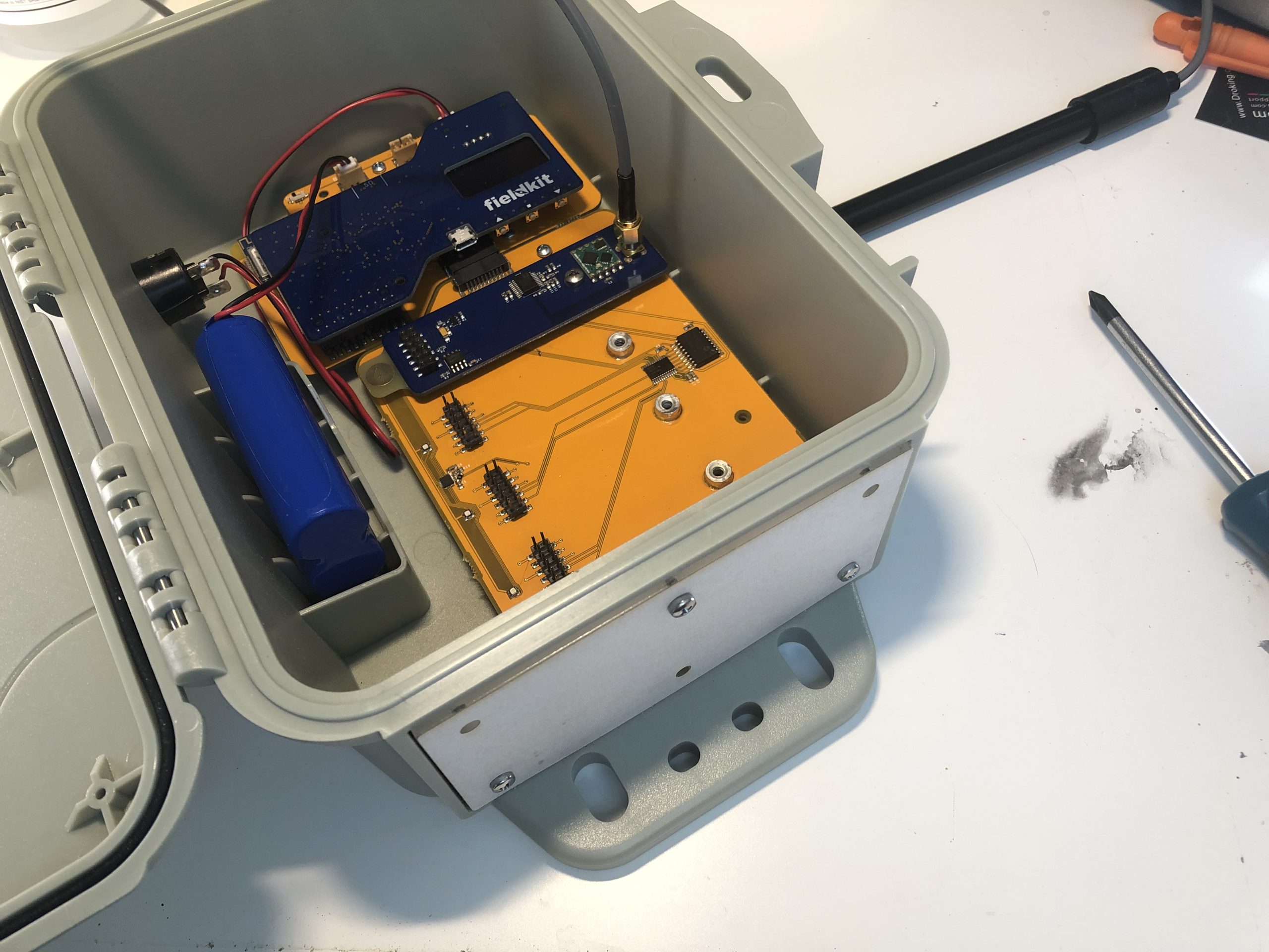
4. Secure Inside Case
Secure your circuit boards inside the Case.
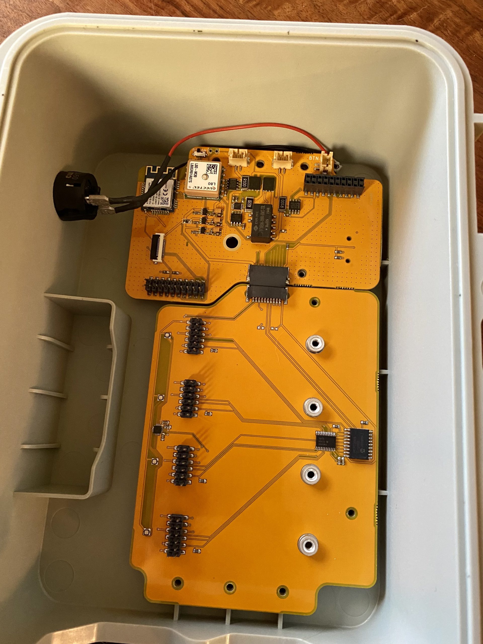
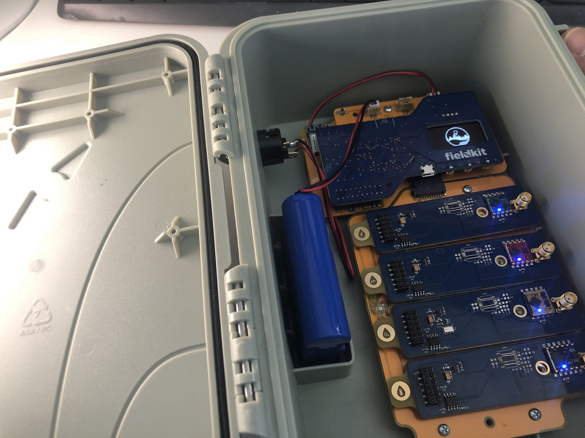
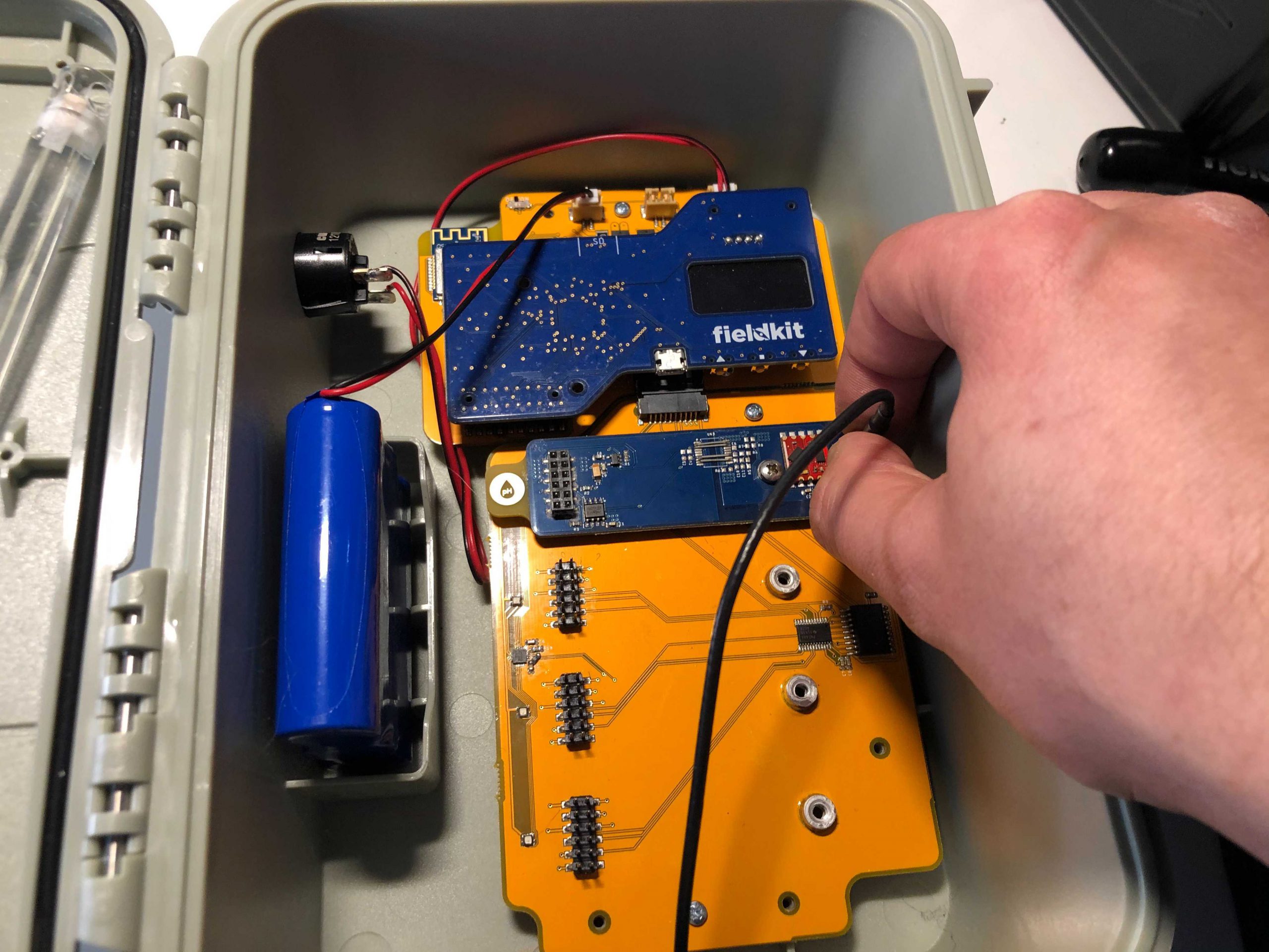
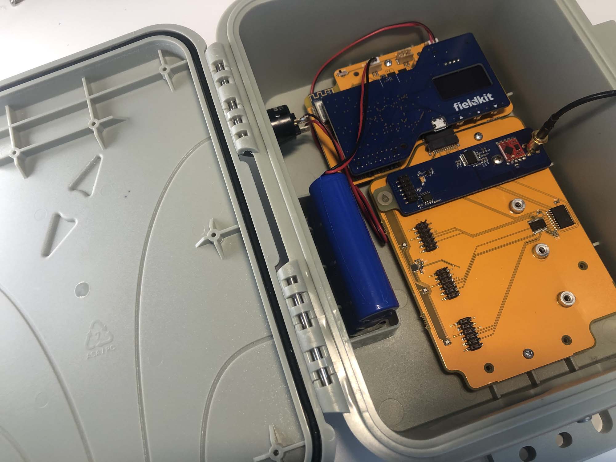
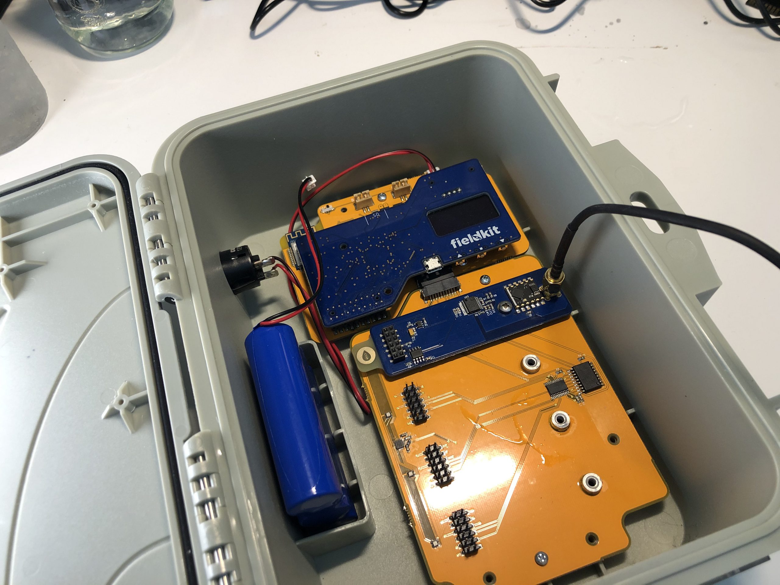
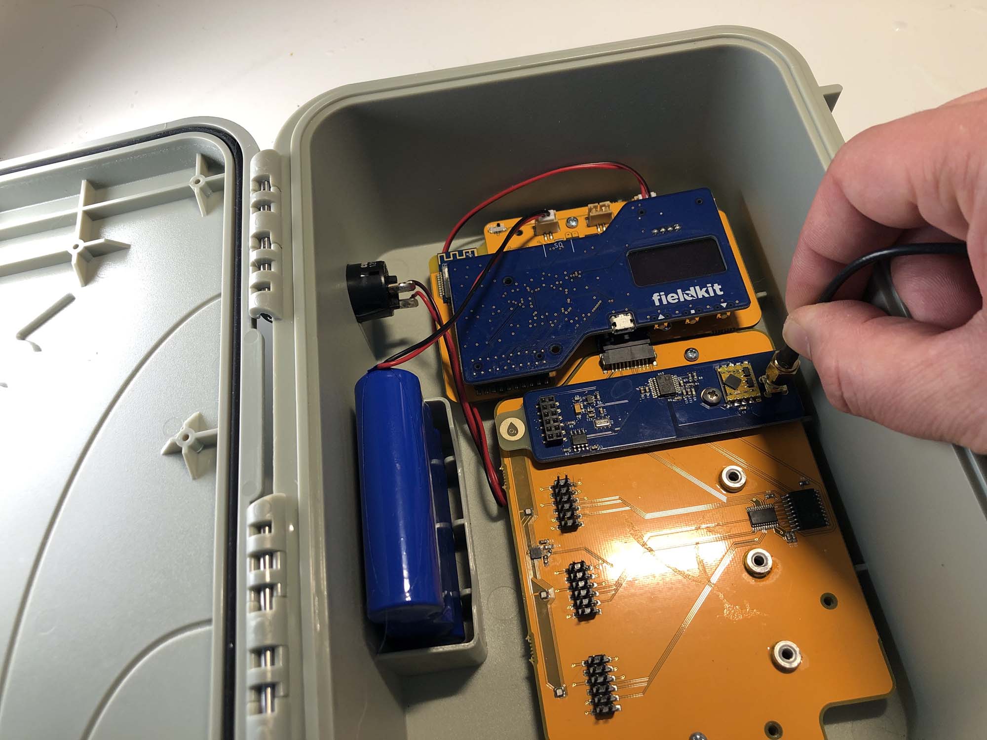
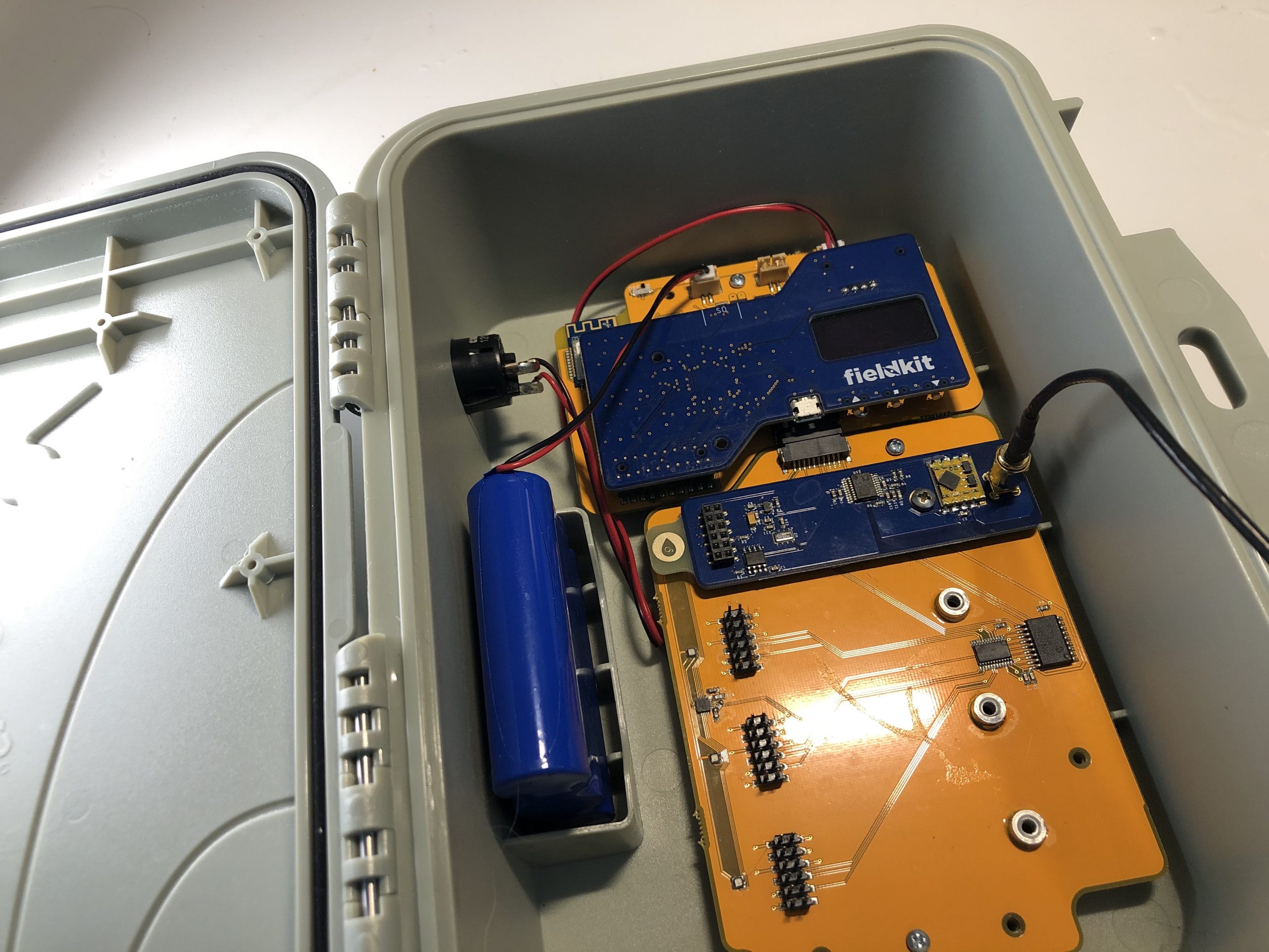
Place Components
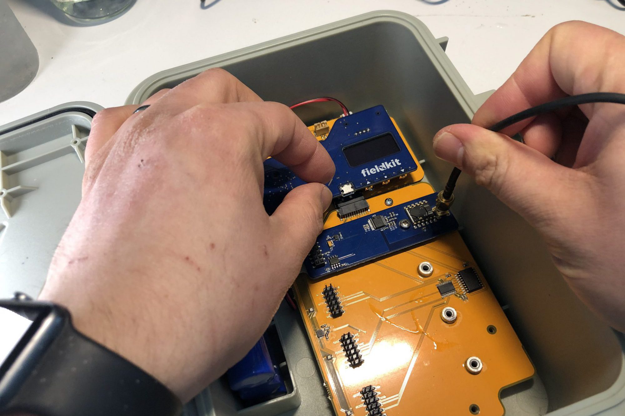
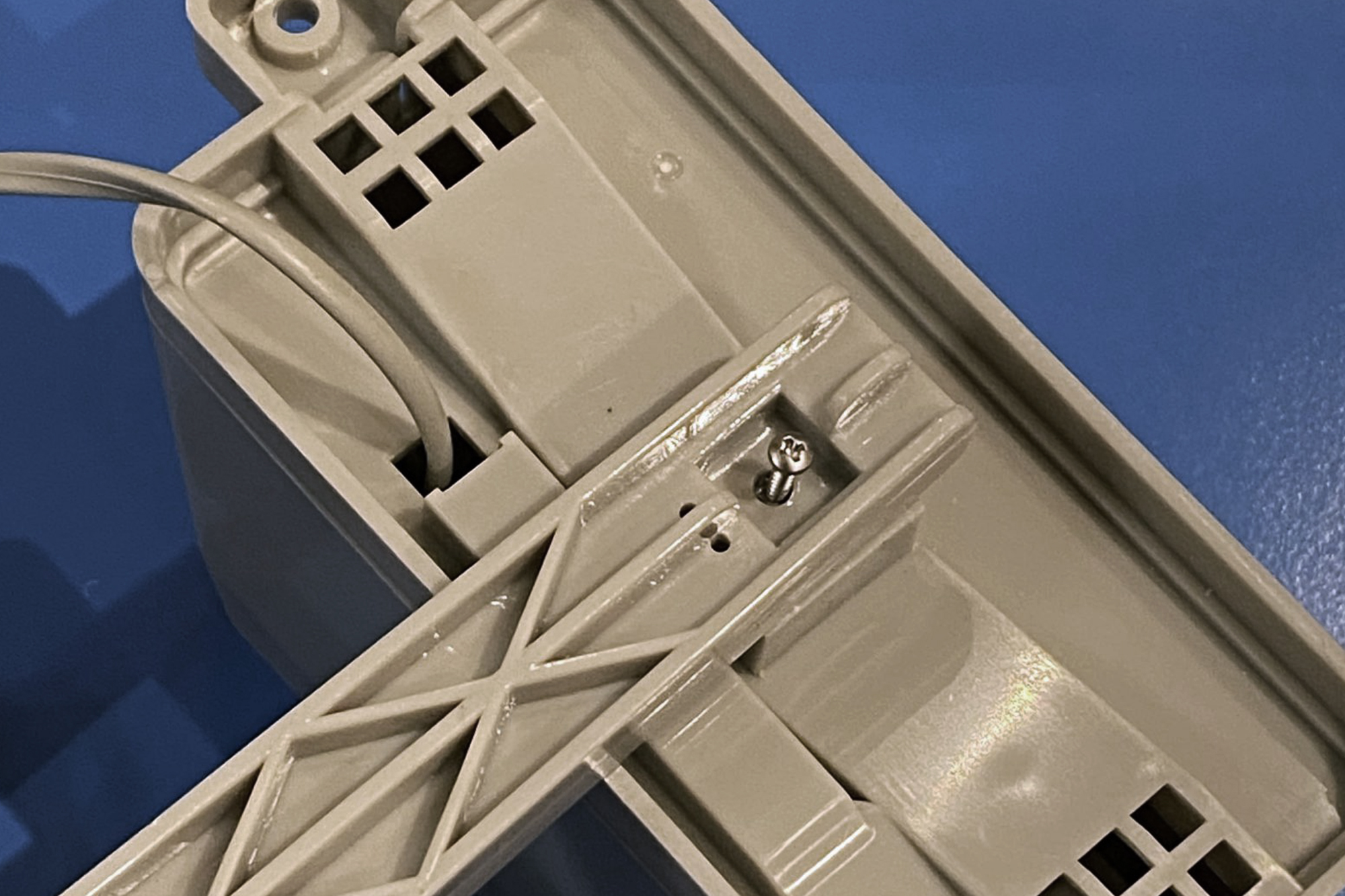
Place your assembled components inside the Case. The wire coming out of the WiFi button on the left can be run along the boards at the top and then re-emerge on the right side, as pictured.
Screw Down the Boards
Secure everything down with the included screws (in the packet marked ‘Core to Case Screws’) so that the hardware doesn’t move around and risk damaging the boards.
Got Them All?
Make sure you’ve screwed in the screws that will be covered up once you put the Upper Board and Module Boards on.
Note: We recommend screwing down all nine screws for maximum security.

These Screws Feel Too Tight!
The screws might feel as if they’re too tight as you screw them into the plastic for the first time. They are thread forming screws, so expect some resistance as you’re screwing the threads into the smooth plastic.
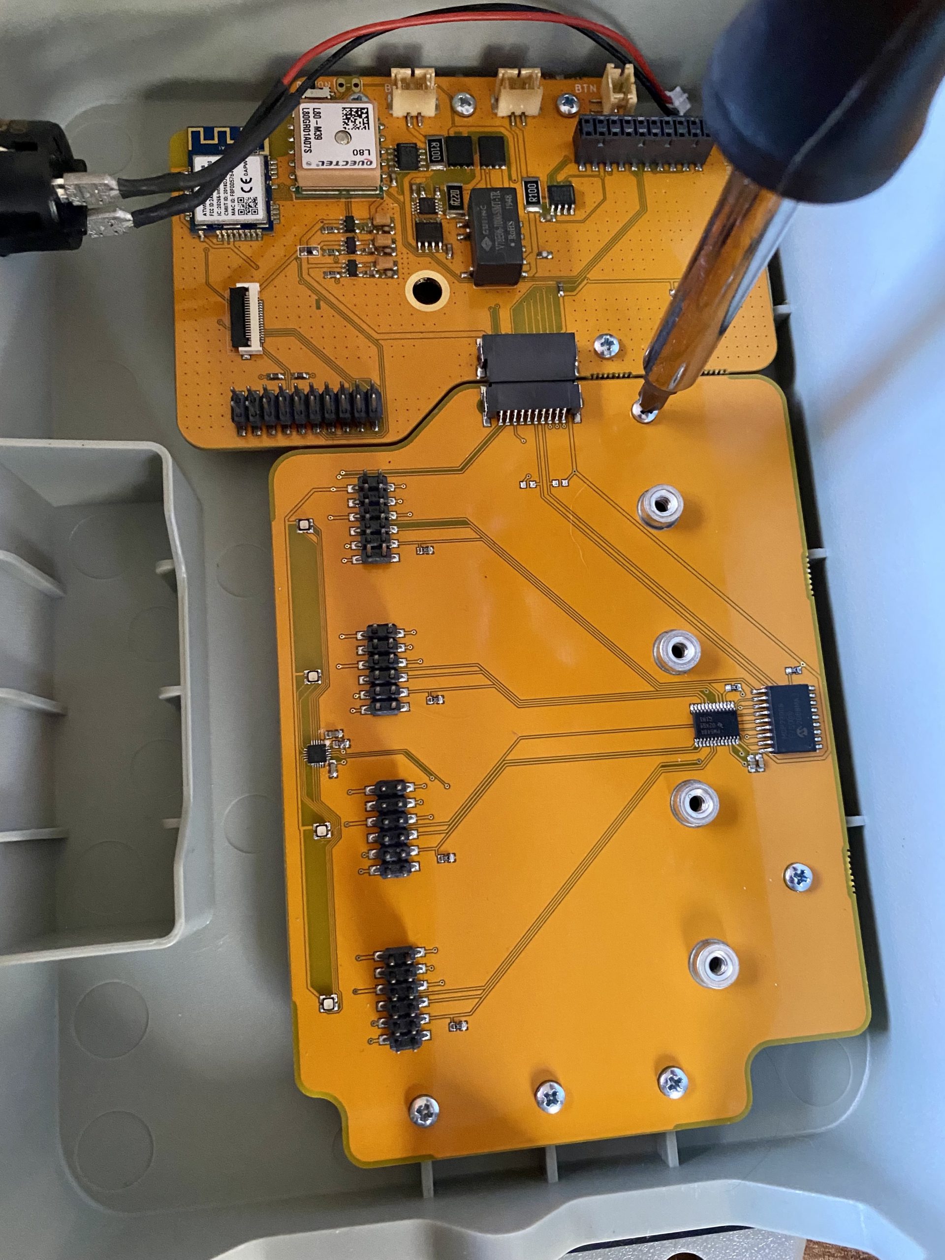
5. Place Upper Board
Now it’s time to replace the Upper Board on top of the Lower Board.
Take the Upper Board
Locate the Upper Board that you previously set aside.
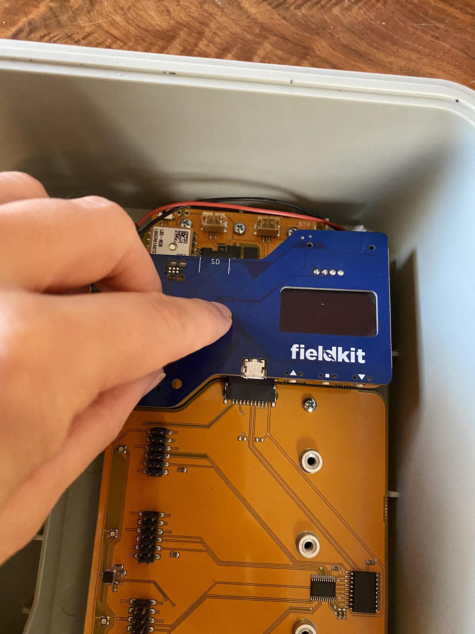
Line Up
Hover the Upper Board above the Lower Board that is now secure in the case. Be sure to line up the pin headers and sockets.
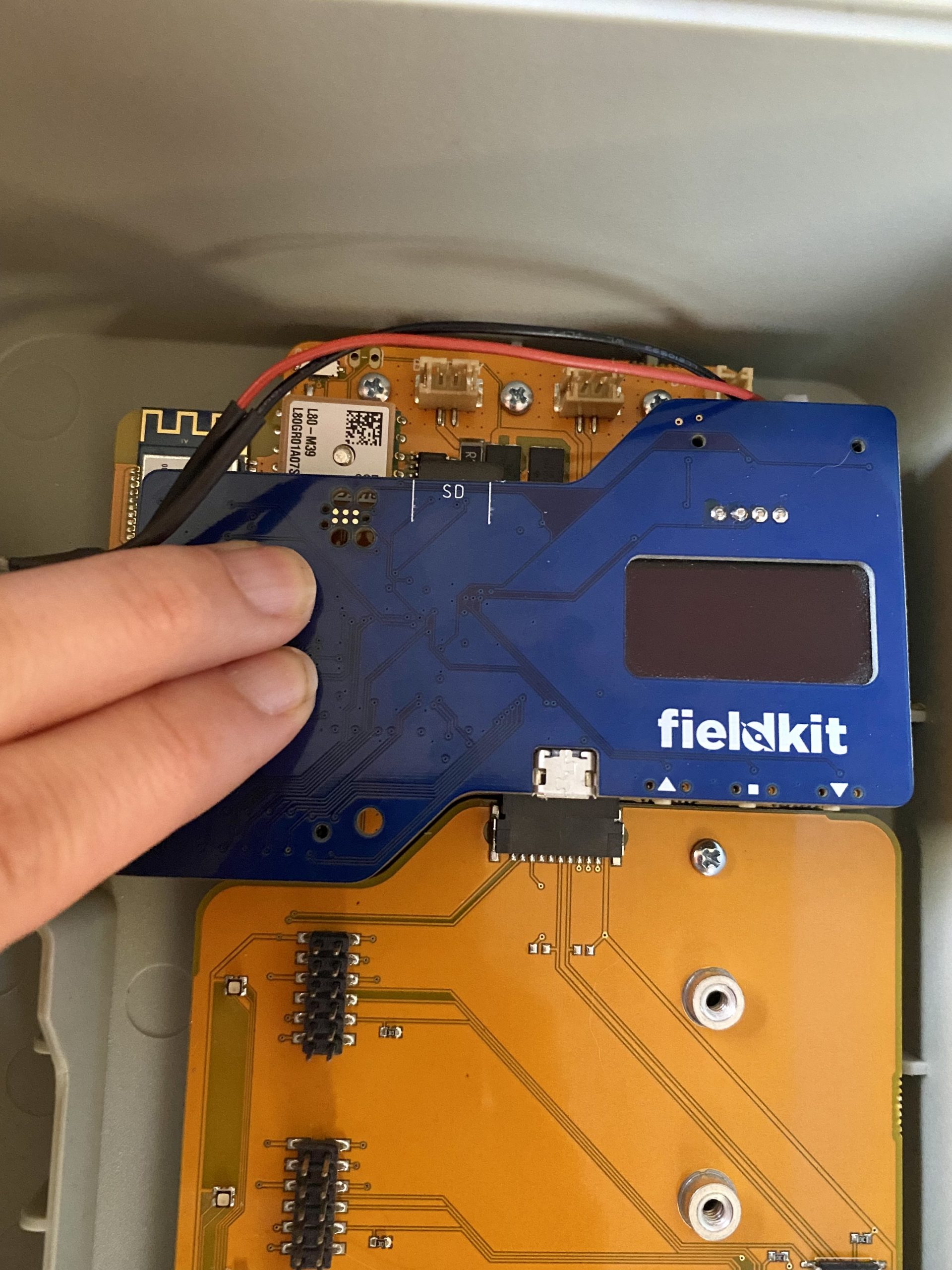
Press Together
Then press them together firmly.
Use caution to avoid bending the Lower Board and Module Base pins, and make sure the pins never touch each other, as it could damage the board.
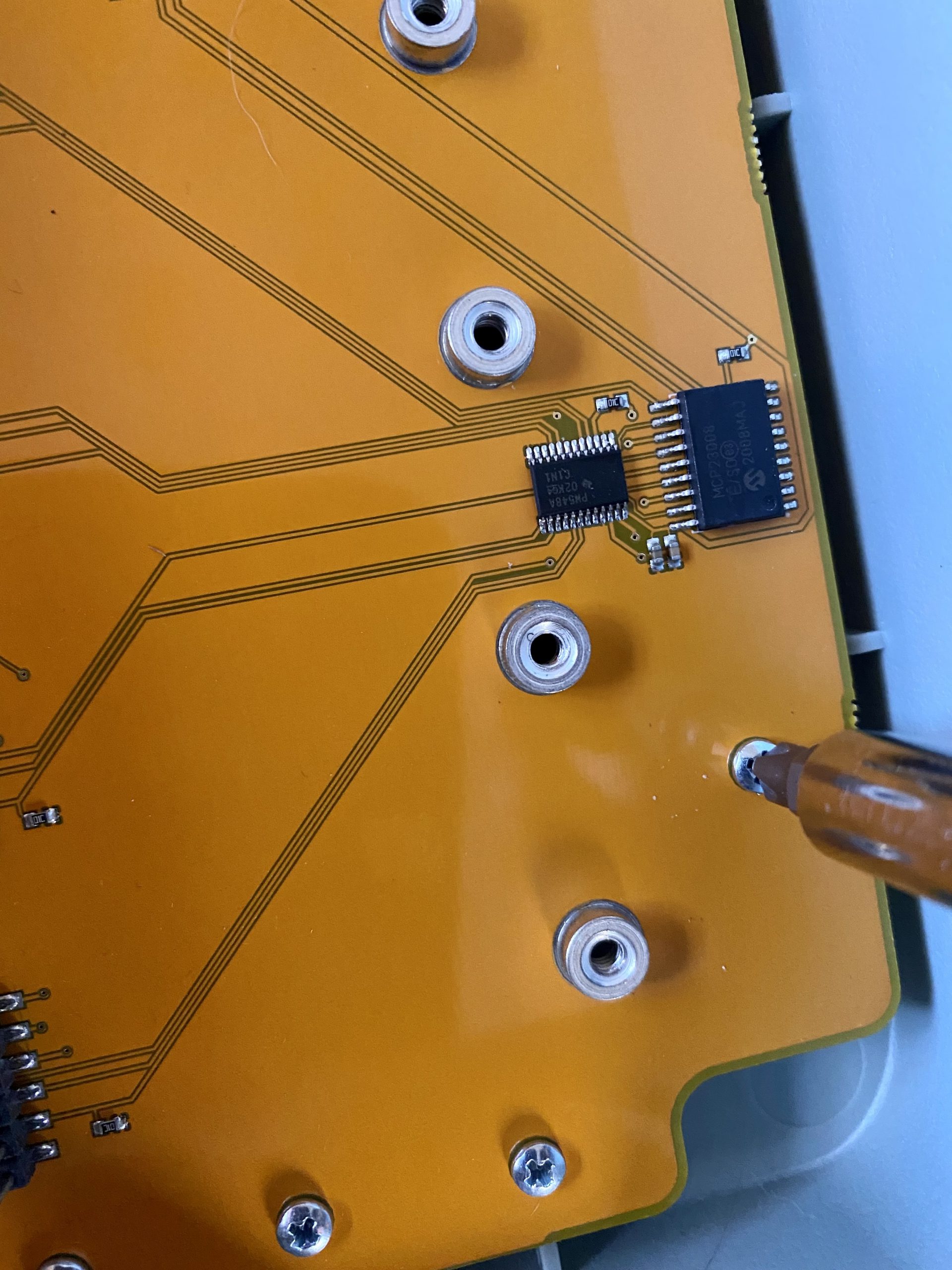
6. Attach Module Boards
Now add your Module Boards. You’ll find your Module Board(s) in the Sensor Pack(s) you bought.
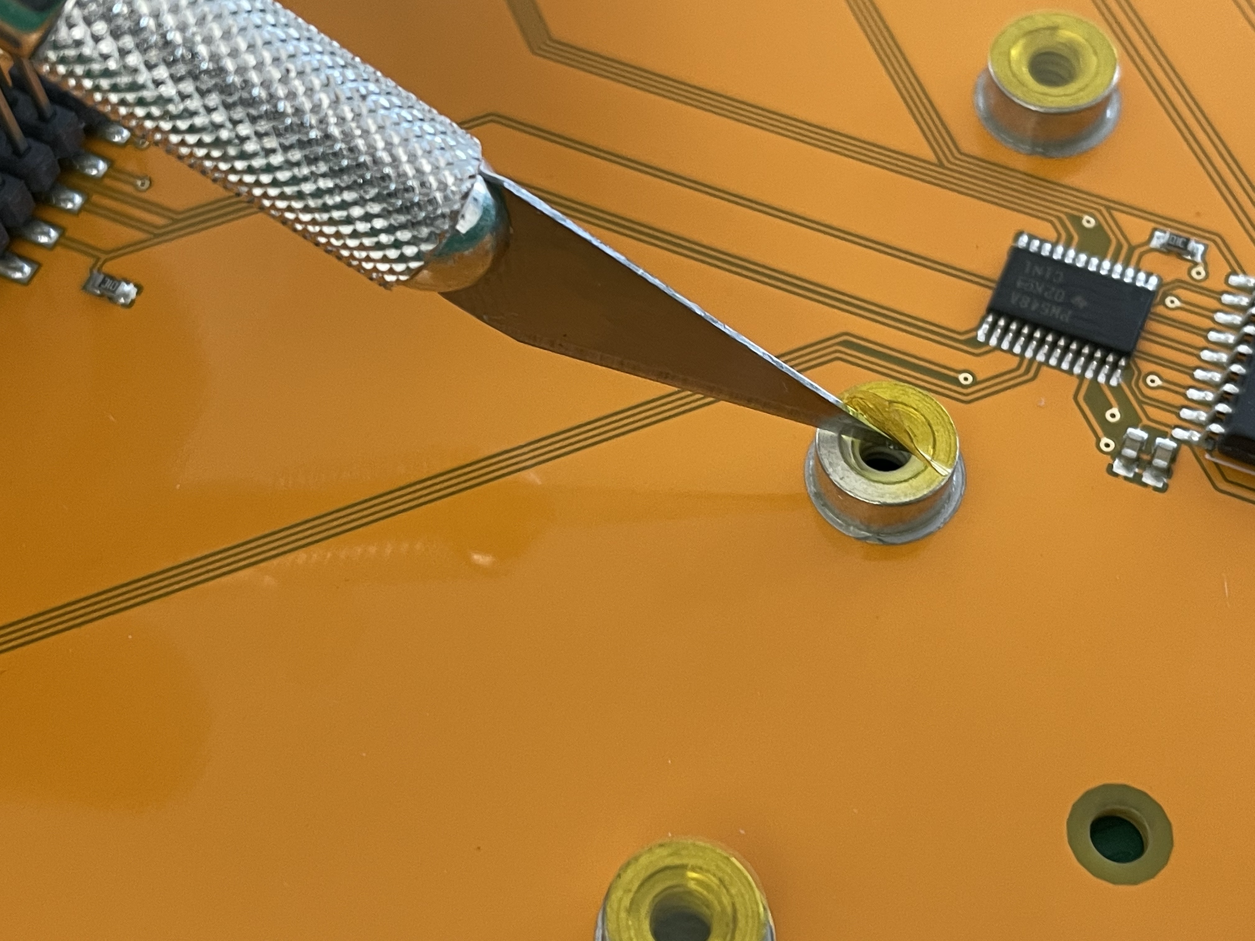
Remove Tape Circles
Remove the small transparent yellow tape circles from the standoffs where you’ll attach your Module Board(s) to the Module Base.
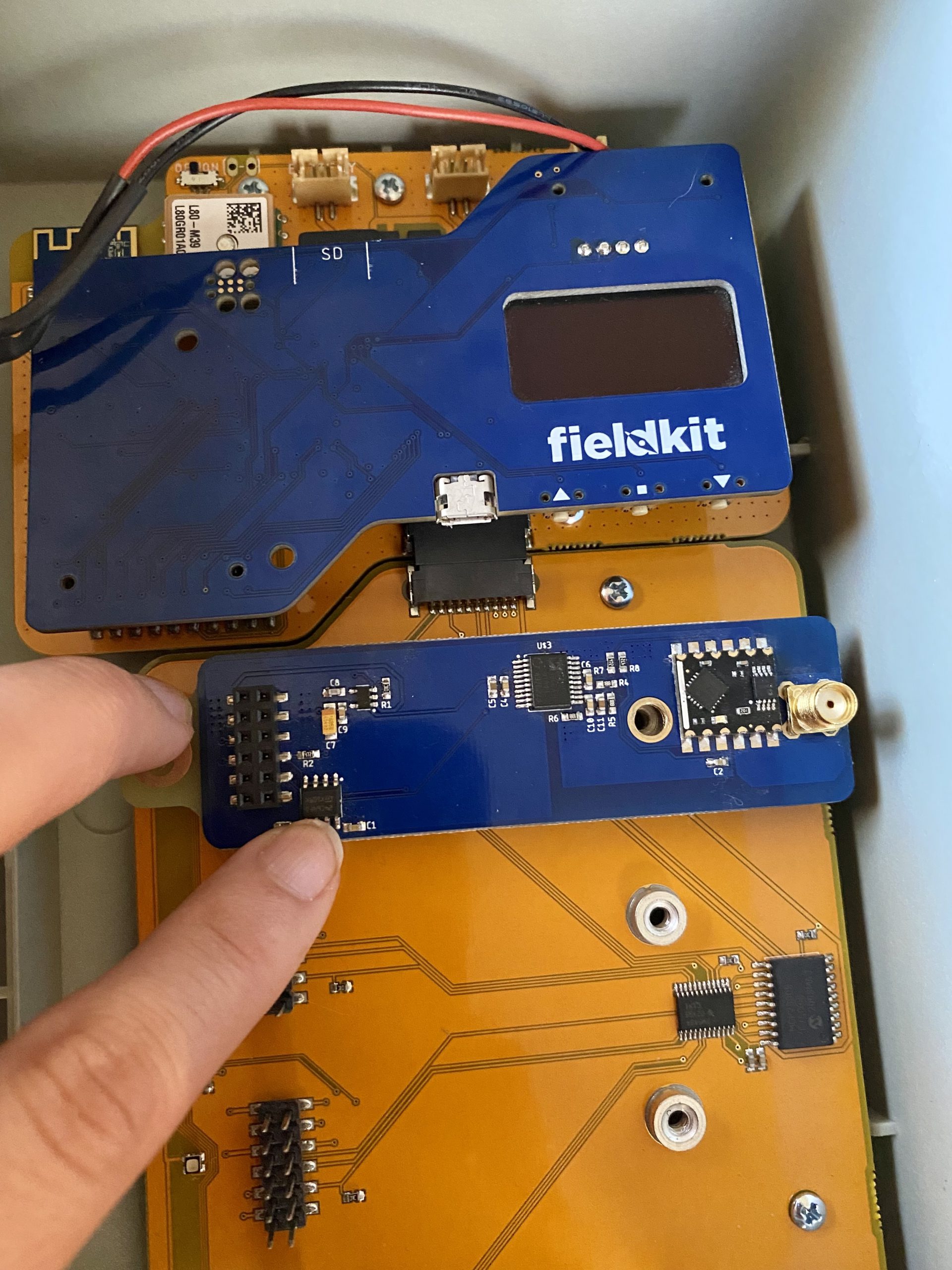
Line Up and Press Down
Line up the Module Board with the pins on one of the bays on the Module Base. Carefully press down the Module Board into place over the pins, applying gentle, even pressure.
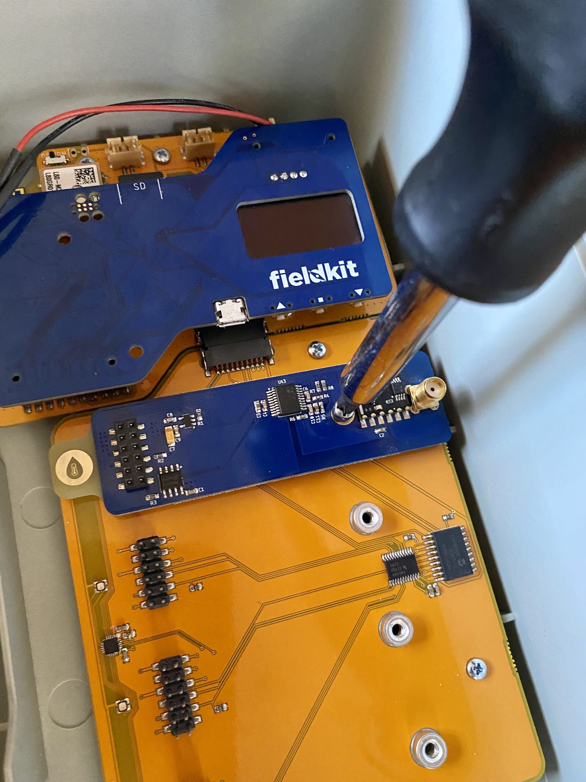
Screw Down the Module Board
Secure it down with the included screws (in the packet marked ‘Module Board Screws’). Repeat with all Module Boards.
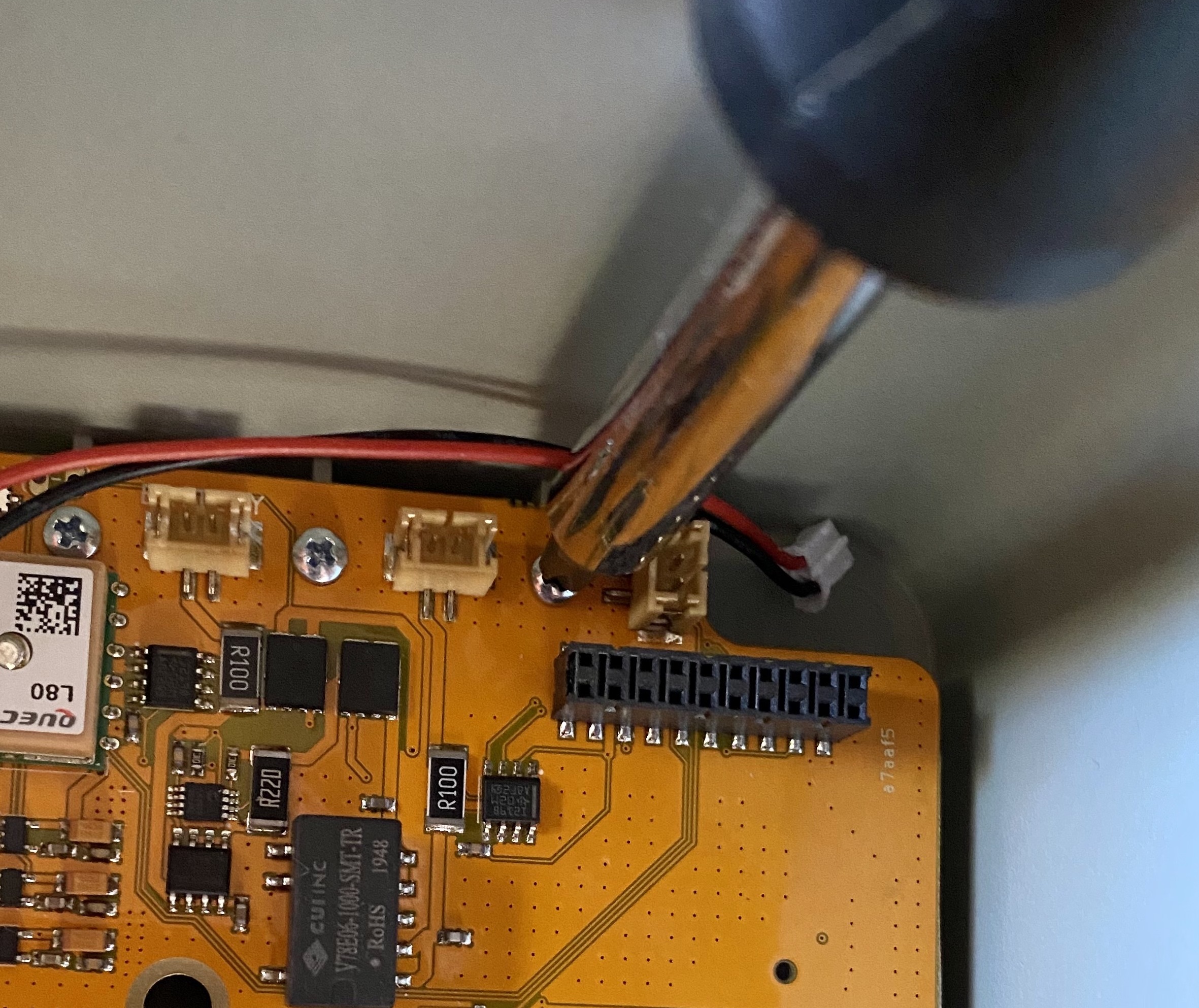
7. Attach Battery
We’ve designed the FieldKit Case with a battery holder to store the Battery.
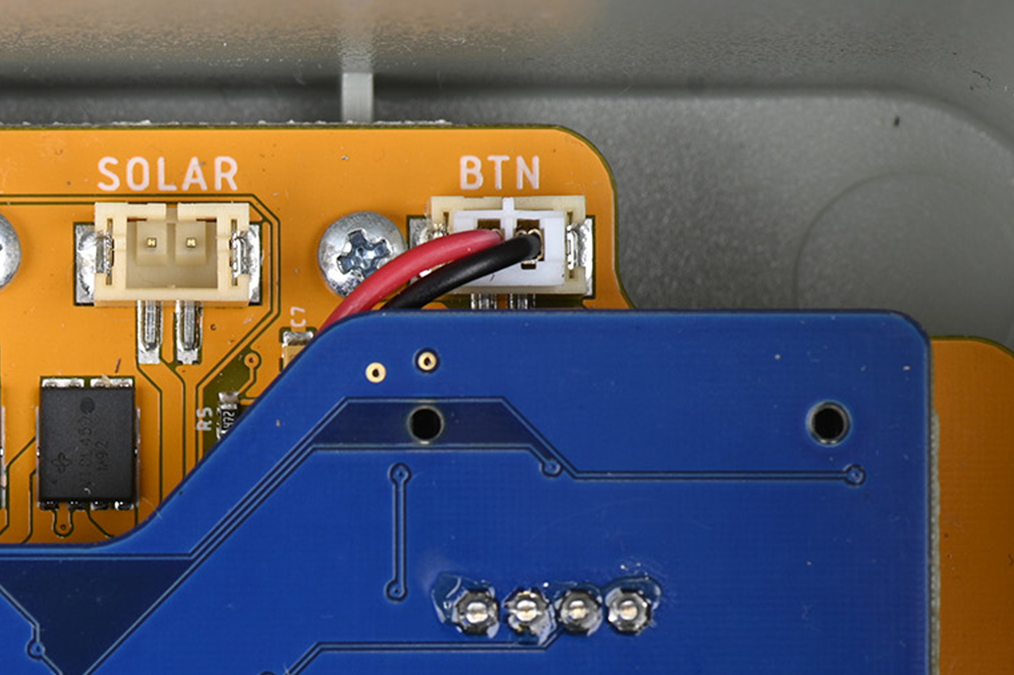
Before inserting the battery, solar and button cables, double check that you are connecting them to the correct sockets (labeled “BATTERY”, “SOLAR” and “BTN”). Inserting cables into the wrong sockets can permanently damage your FieldKit.
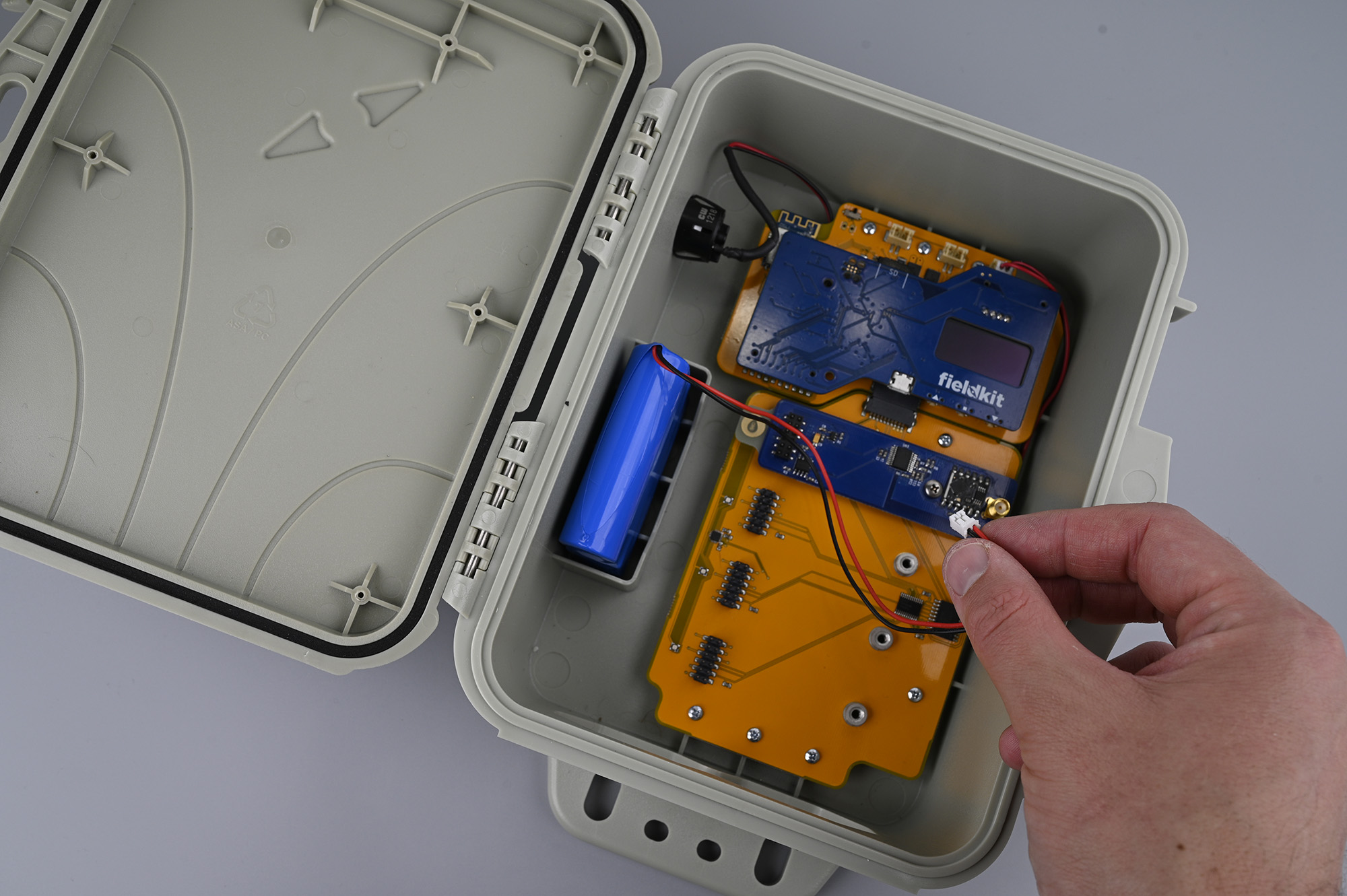
Place Battery Into Battery Holder
Place your Battery into the battery holder on the left hand side of the core.
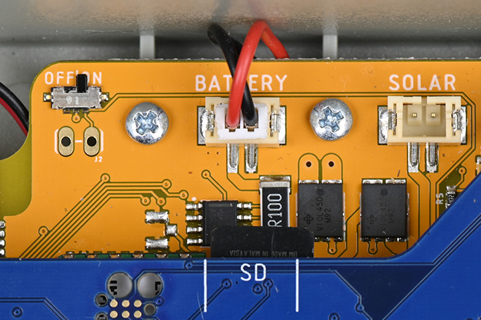
Insert Battery Cable
Insert the red and black battery cable into the socket on the top left hand side of the Upper Board where it says “BATTERY”.
8. Attach Button
Everything is better with a big button!
Before inserting the battery, solar and button cables, double check that you are connecting them to the correct sockets (labeled “BATTERY,” “SOLAR” and “BTN”). Inserting cables into the wrong sockets can permanently damage your FieldKit.
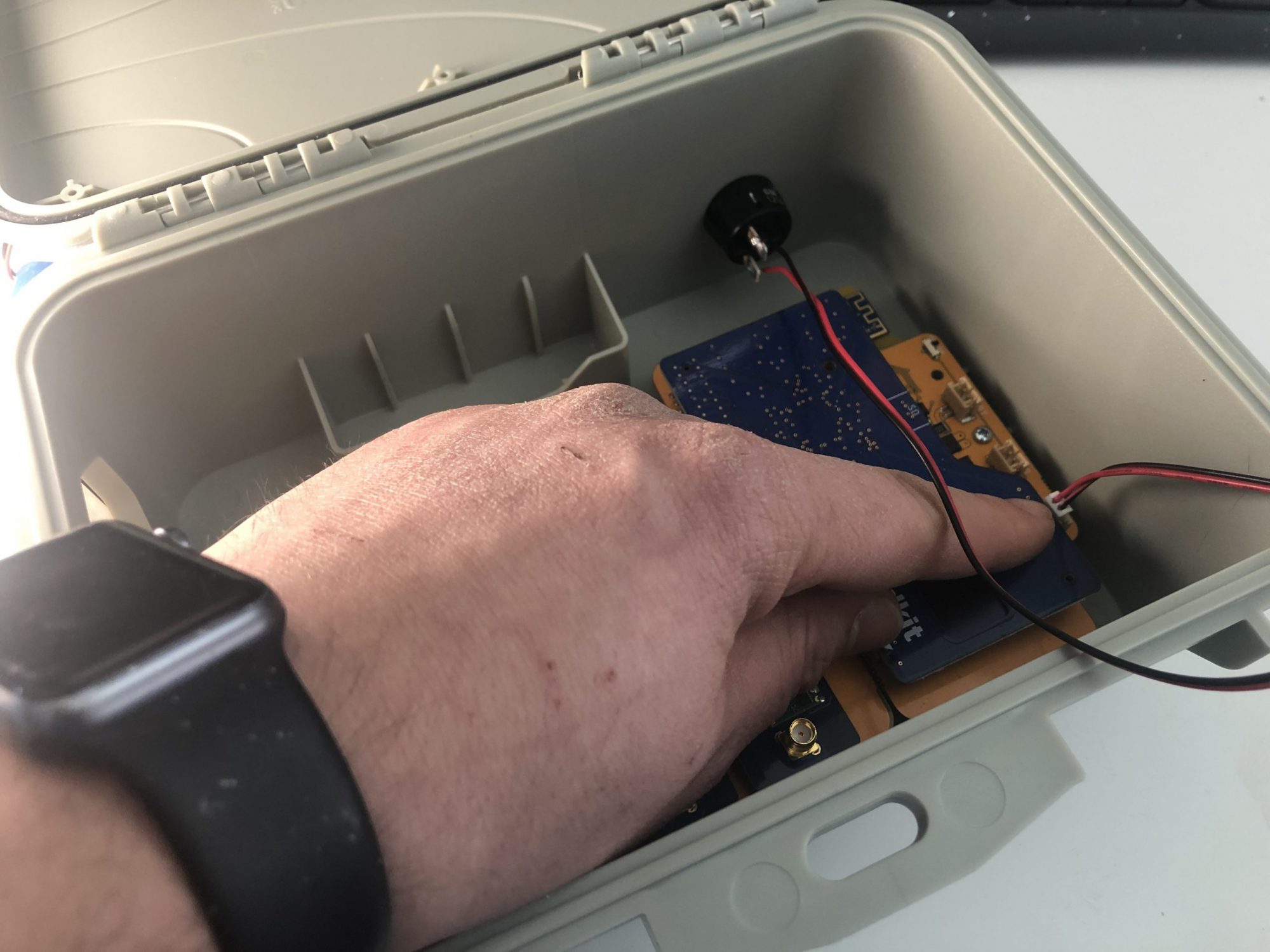
Locate the Button Cable
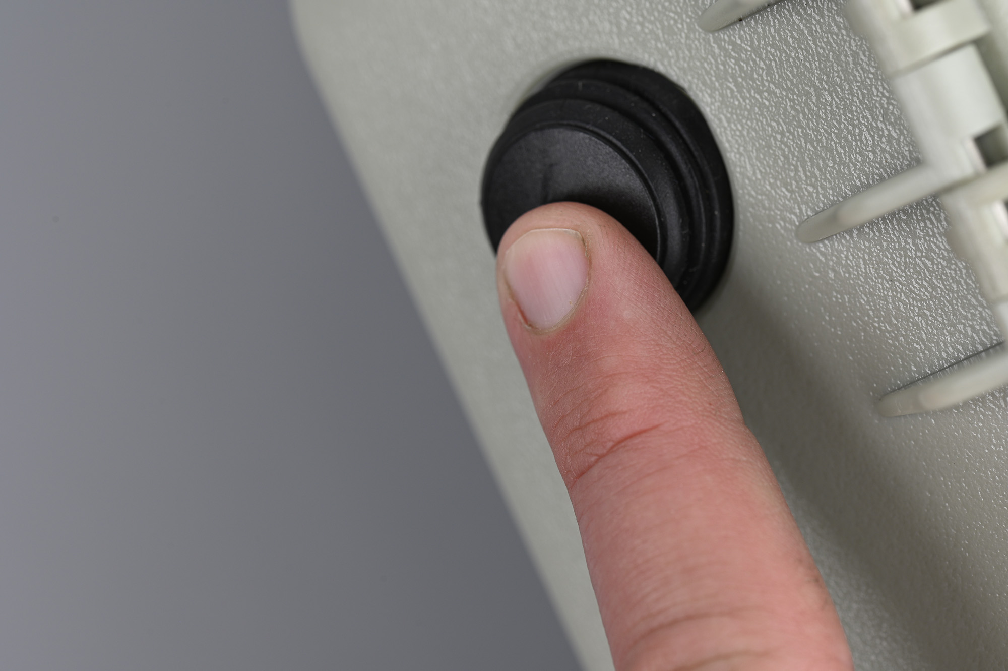
On the left hand outer wall of the Case, you’ll see a big black button. This is the Wake Button that you’ll later use to wake up the station and turn on the Station WiFi signal.
If you follow the button into the interior left hand wall of the Case, you’ll see two metal prongs with a red and black cable attached. That’s the button cable.
Insert Button Cable
Take the button cable and insert it into the socket on the top right hand side of the Upper Board where it says “BTN”.
9. Plug in Micro-USB Cable to Charge Station
Time to power up!
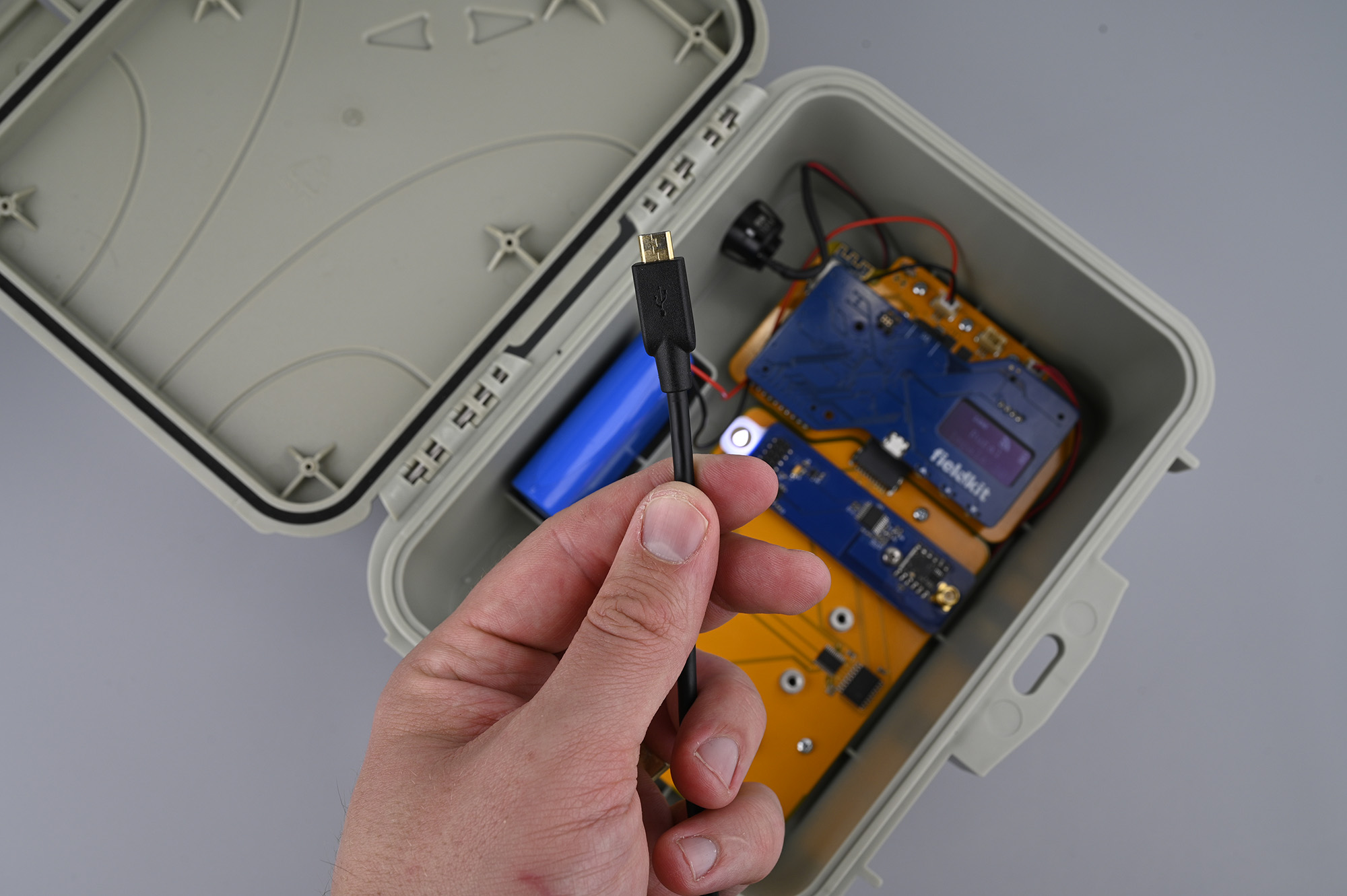
Locate the Micro-USB Cable
As part of your station, you’ll find a black Micro-USB Cable that you will use to charge the Battery.
Plug in Cable to Charge Station
Plug in the Micro-USB cable to a power source (e.g. a USB wall charger) to start charging the Battery. Your station takes 6-12 hours to fully charge, and it should be fully charged before you deploy. It charges faster when switched off.
If you have issues charging your station, potential culprits could be the USB charger, using a cable other than the one provided by FieldKit, or using a USB battery bank. For recommendations on what kind of charging equipment to use, please see this item in our FAQ.
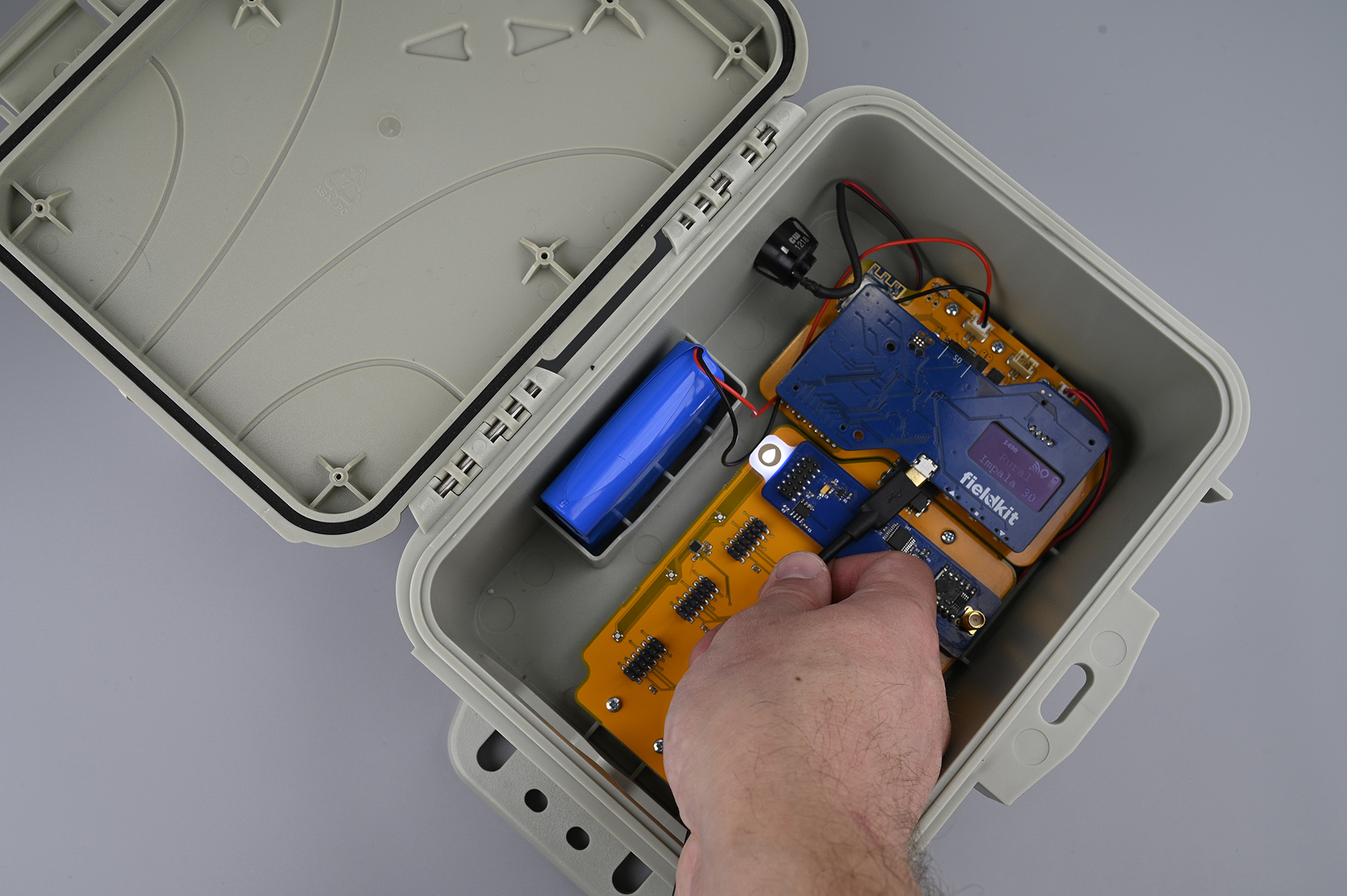
10. Switch On to Connect
It’s almost time to connect to your station!
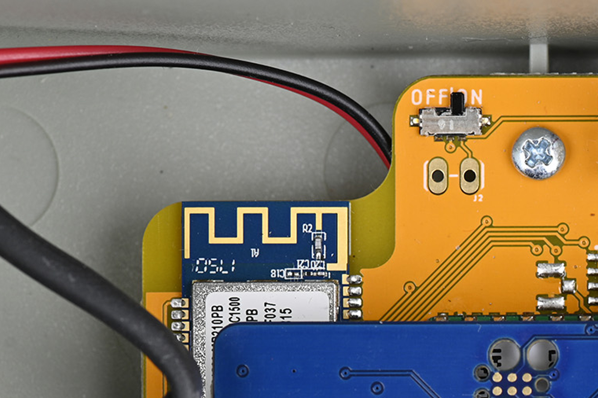
Switch On
Flip the small switch in the top left of the Upper Board to the “ON” position, so your FieldKit station comes to life, and you’re ready to connect.
You can do this with either the tip of your finger or your fingernail, or even the tip of your screwdriver.
Screen Display Turns On
Once you’ve turned it on, the screen display turns on and the display startup sequence begins. The Conservify logo appears briefly followed by the station name and startup diagnostics.
Once the station has successfully booted up, the display turns off after a few minutes. Pressing any button below the screen (or the Wake button) turns the display back on. After a period of inactivity, the display will then turn off.
The system charges whether switched on or off, but having the station switched on allows you to intermittently check battery life on the station screen.
Connect Station
Connect your phone to your FieldKit station to collect and view data.
If after following the steps below, you still have trouble connecting to your station, check out our article on troubleshooting connection issues here.
1. Turn on Station WiFi
Your station has an access point with its own WiFi signal. It acts like a hotspot so you can connect to it via your mobile device and transfer data (note that it does not connect to the Internet).
Press the button to enable the station’s Access Point (AP). WiFi can also be turned on using the menu on the Station screen. See the Station Screen Interface section for more details. This button will also connect the station to the last network it was connected to if a network has been saved in the app’s station settings.
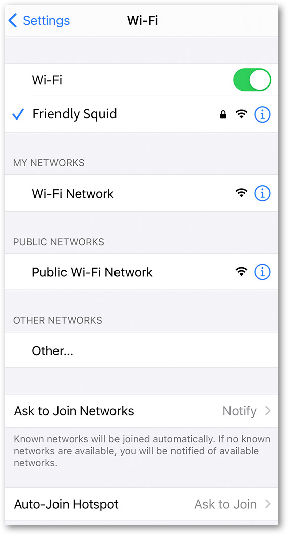
2. Connect to your Station
Go to your mobile phone WiFi settings and select the station name displayed on the station screen. The name will default to a random combination of a descriptive adjective, a name of an animal, and a number, such as Friendly Squid 42 or Gentle Eagle 23.
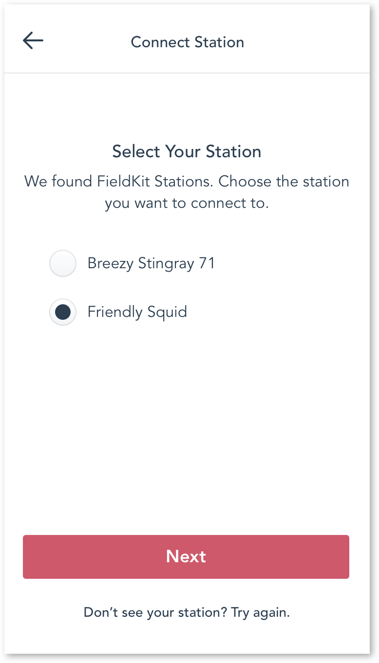
3. Select your Station WiFi in the App
The app automatically will search for nearby FieldKit stations that have their WiFi enabled. Choose the one you are setting up (the same one as the previous step).
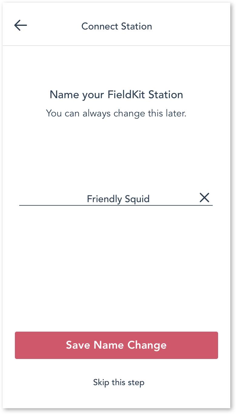
4. Name Station
Once the app confirms that your station is connected, you can choose to name your FieldKit Station something different than the default. Providing a unique name or number for each station can help you personalize and remember each one. You can always skip this part and change your station name later.
Changing your station name will change the Station WiFi name immediately in your phone’s WiFi settings, and upon restart of the station and enablement of the Station WiFi on your station screen.
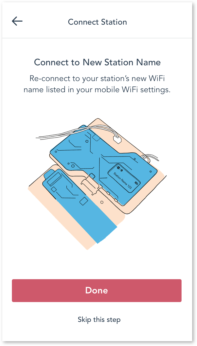
5. Connect to New Station Name
If you have renamed your station, re-connect to your station’s new name as listed in your phone’s WiFi settings.
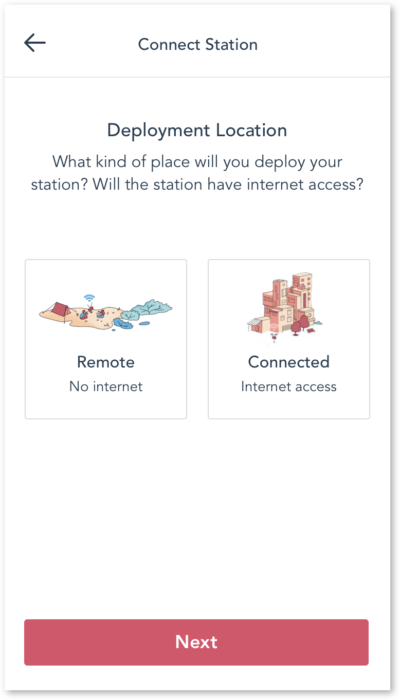
6. Choose WiFi Settings based on your Deployment Location
Choose how to connect and sync data based on your deployment location (you can always update this later in Settings). Think about where you will deploy. Will the station have internet access?
Remote Location (No Internet) → Station WiFi (Access Point)
For a remote location with limited internet access, we recommend using the Station AP. This option syncs station data to your phone only. When you have an internet connection later, you can then use your phone to upload it to the FieldKit web portal.
Connected Location (Internet Access) → WiFi Network (Internet)
For connected locations with internet access, we recommend adding 1-2 preferred WiFi networks to sync station data straight to the FieldKit web portal. If the station is unable to join these networks, it will use its Station AP as a fallback.
The WiFi name and password are case sensitive. Ensure your station is using the new saved WiFi network by pressing the right-hand button under the station’s screen once. You will see the name and IP address of the network the station is using, or “WiFi Off” if the station has turned off its network to save power.
7. Connecting in the Future
If returning to a station after days, weeks or months, the FieldKit app should be able to detect the Station WiFi and connect automatically after hitting the Wake button. In situations where the mobile app and station do not auto-detect one another, open up your phone’s WiFi settings to reconnect. For more information on this, see the Sync Data section.
In Station Settings > Networks > WiFi > WiFi Duration you can enable Station WiFi to be “Always On” by setting a data upload schedule for your station to upload data straight to the web portal (bypassing the app). To preserve power, “Always On” should only be used with stations that are plugged into an external power source, rather than using the battery alone or in conjunction with a solar panel.
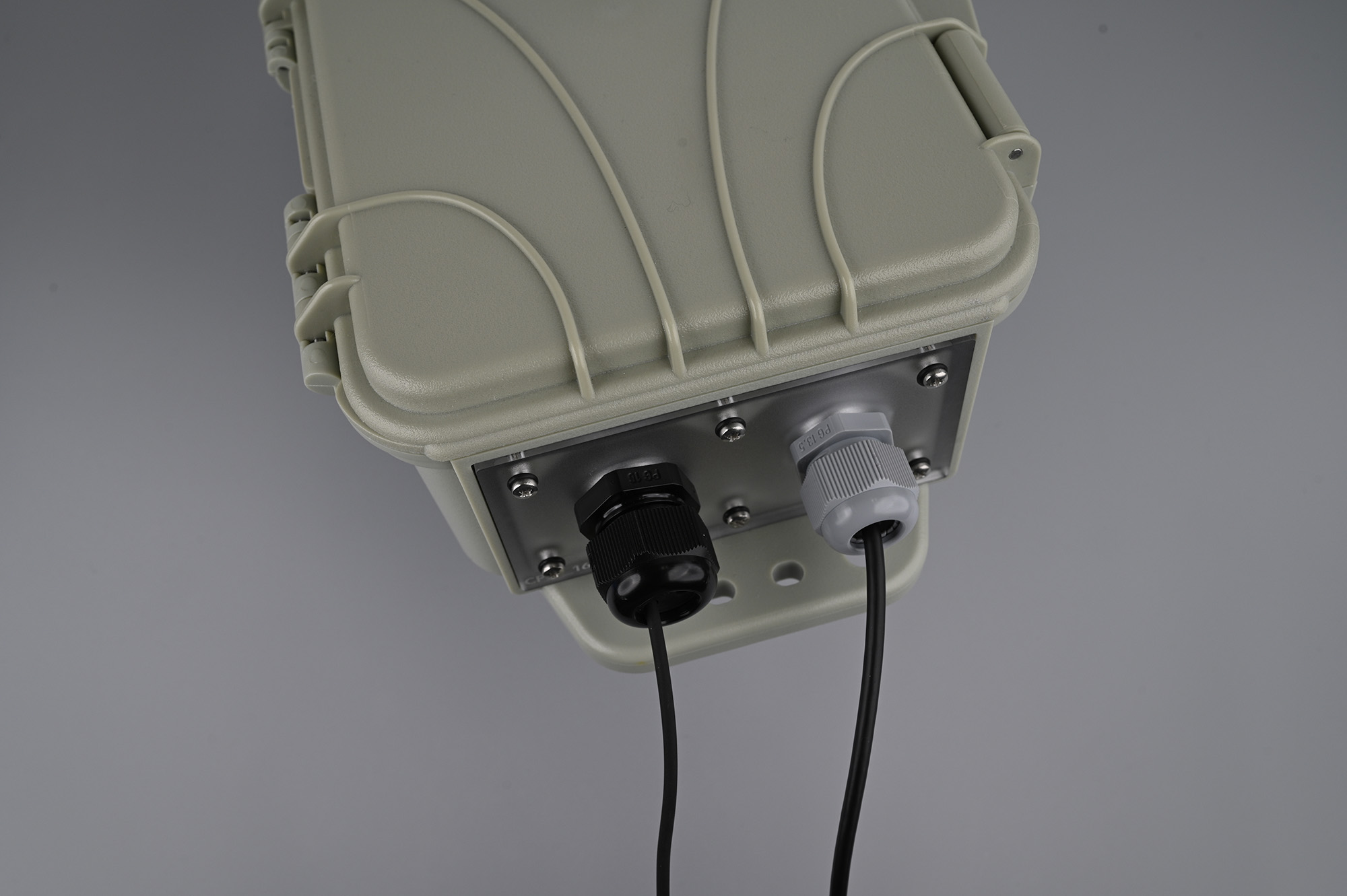
Assemble Cable Plate
Cable Plate assembly depends on your sensor and power configuration.
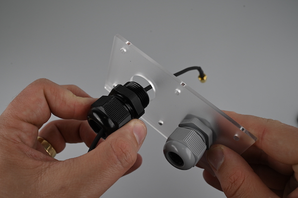
The Cable Plate Pack is designed to fit onto the FieldKit Case, and includes a plastic Cable Plate with custom glands and cable inserts, allowing specific configurations of cables to pass into the case. The Cable Plate best suited for your needs will depend on your intended sensor and power configuration, therefore don’t worry if your glands don’t look exactly like the images below.
This process can be pretty involved, so you might choose to do this as part of the next step, sensor module setup, or at the very end of station setup. Either way, you can complete the steps in this section when it makes sense for you. Ensure your FieldKit Core is screwed into the case before beginning cable plate installation.

Confused about cable plate configurations? Check out this table.
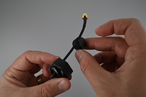
Note that when assembling the Cable Plate, the gland for the power cables (if used) generally goes on the left side of the plate and the gland for the sensor cables goes on the right.
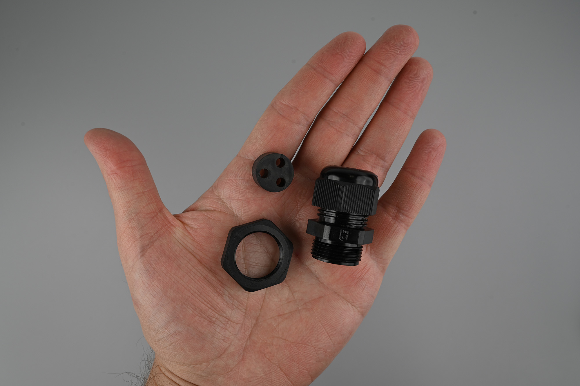
1. Take your Components
Collect your gland components.
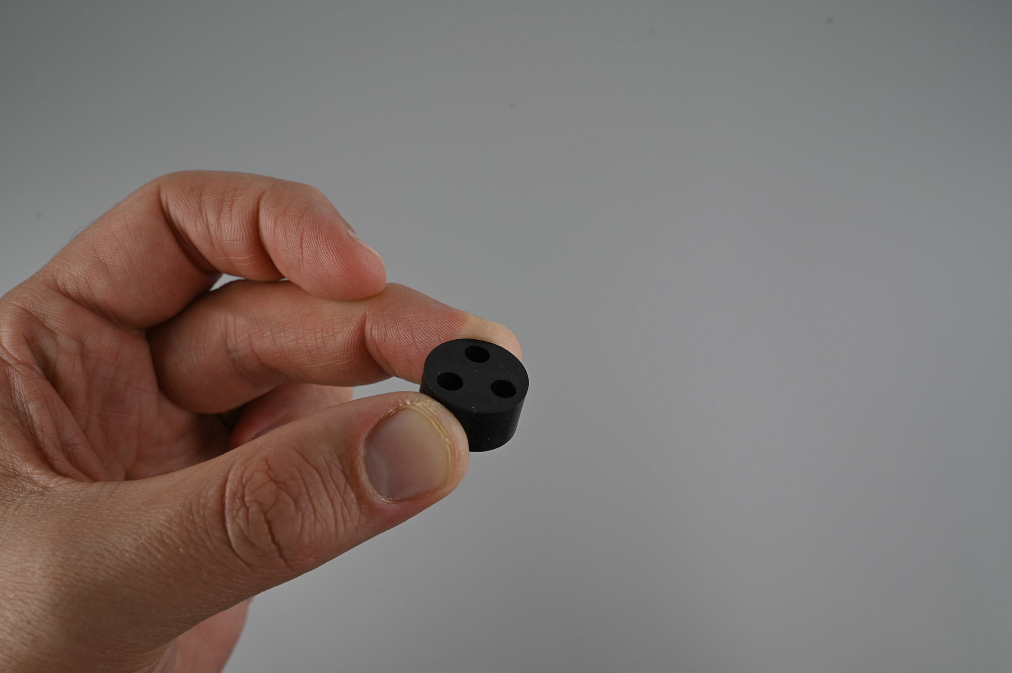
2. Remove Insert
Remove the front cap on the gland and remove the insert. For glands with a free floating insert, skip this step. Additionally, you will not need to remove nor modify the insert in the 1 CAT5 cable plate gland used with the FieldKit weather module, so you may disregard steps 3, 4, and 6 below in that case.
If your gland came with a multi-hole insert, also look inside the gland and remove the large ring-shaped insert that comes inside. If you have issues fitting the multi-hole insert into the gland, this additional ring-shaped insert is likely the culprit.
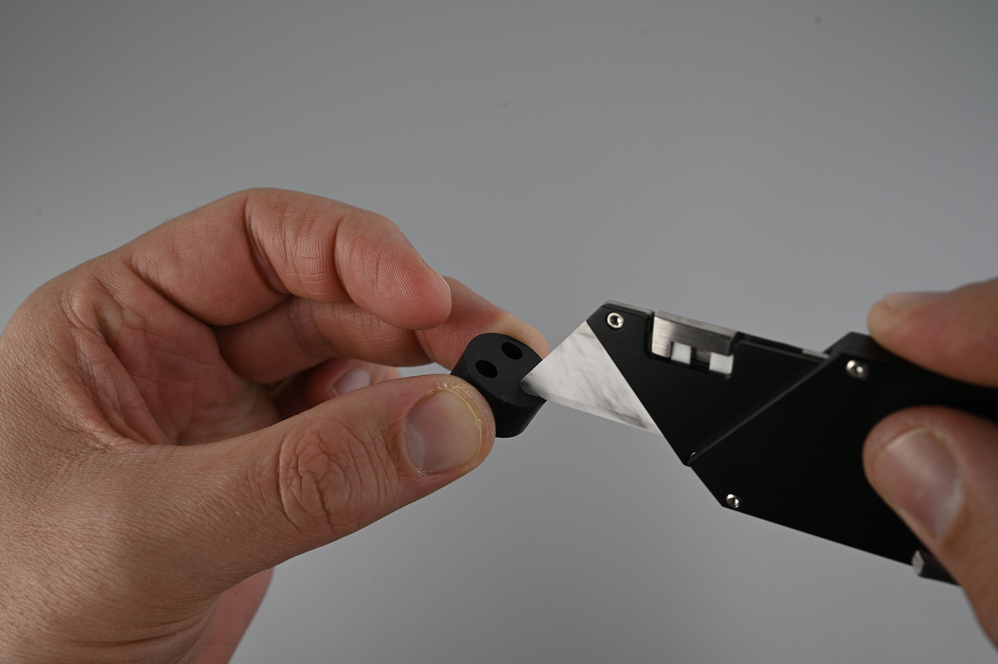
3. Cut Slit in Insert
The cable connector is too wide to thread through the diameter of the insert hole. Therefore, you’ll have to cut a slit next to each insert hole to provide a way for the cable body (the thinner part) to slot in from the side.
Using scissors or a box cutter knife, carefully cut a slit that runs from the outside of the insert to the outer edge of the hole for each cable. Please take appropriate safety measures.
4. Thread Cable through Cap
Run the cable connector that plugs into the module board through the front cap (front to back).
5. Slot Cable into Insert
On the far side of the cap, slot the cable into the insert hole sideways using the slit you’ve just cut.
Repeat steps 3-5 as necessary for all cables going through that insert.
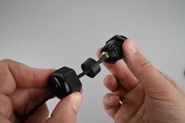
6. Add Insert to Gland
Now that the insert is attached to the cables, thread them into the gland body, front to back, so they exit the locking nut.
7. Secure Insert
Softly screw on the front cap to hold the insert loosely in place.
8. Set Gland into Cable Plate
Remove the locking nut from the back of the gland, insert the threaded side of the gland into the cable plate hole.
Note that when assembling the Cable Plate, the gland for the power cables (if used) generally goes on the left side of the plate and the gland for the sensor cables goes on the right.
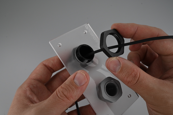
9. Lock Gland into Place
Replace the locking nut, tightening until it stops.
Repeat the above steps as necessary for all glands.
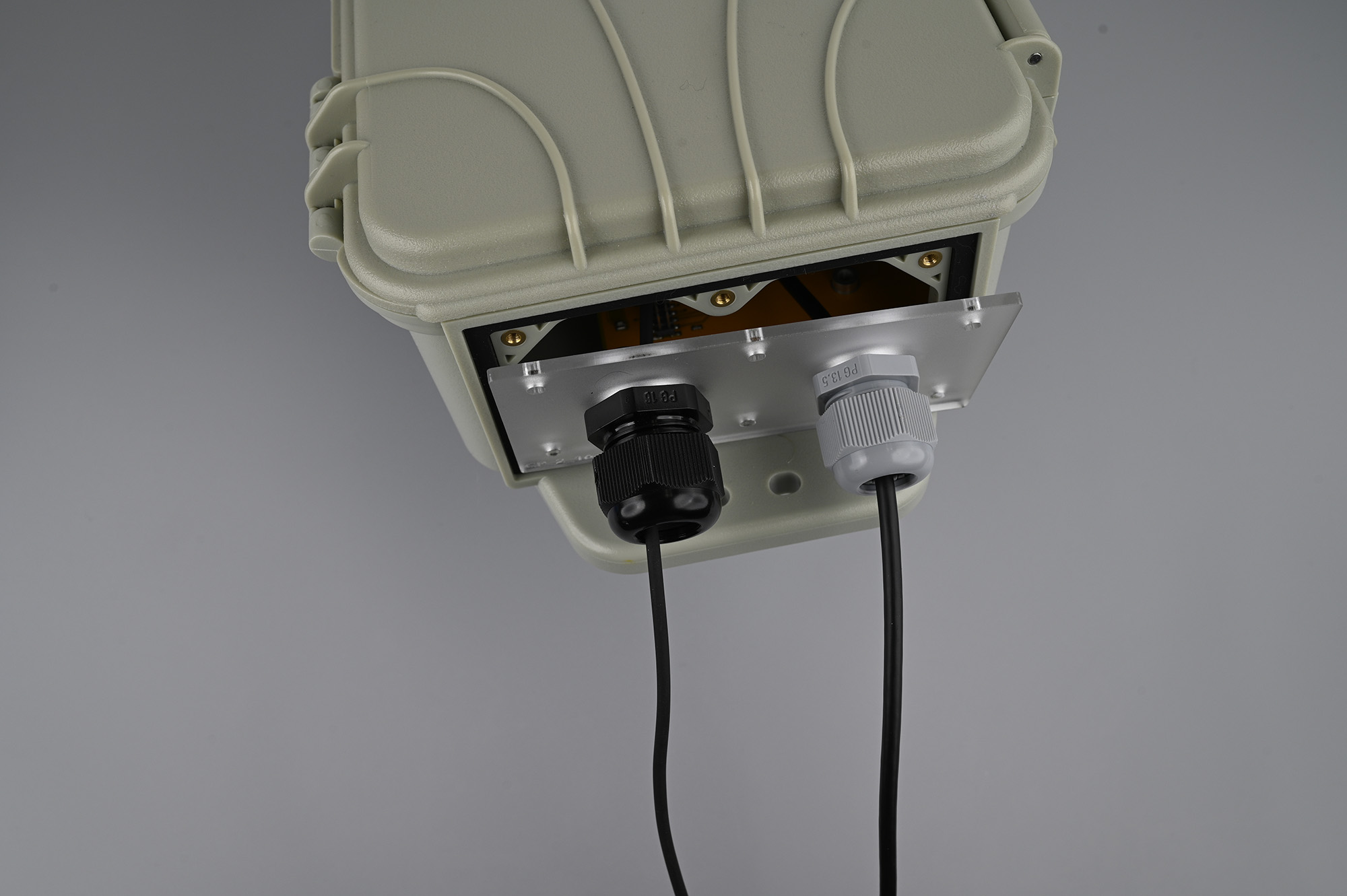
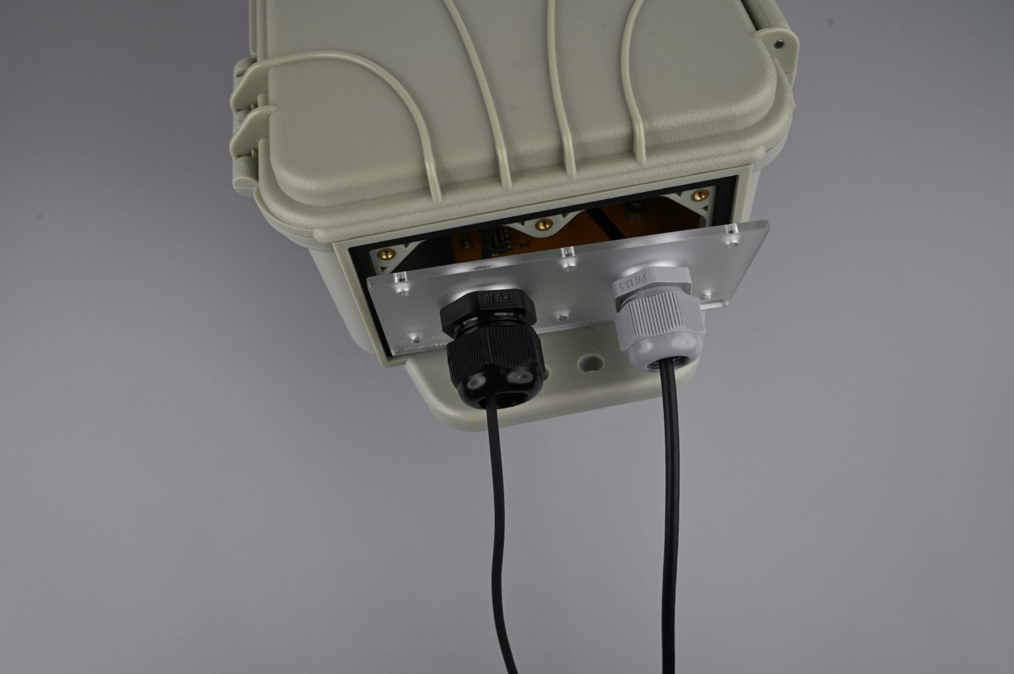
10. Position Cable Plate
Once all your cables with inserts are in their respective glands and attached to the cable plate, you’re ready to screw your cable plate into place on your case by tightening the locking nut back into place.
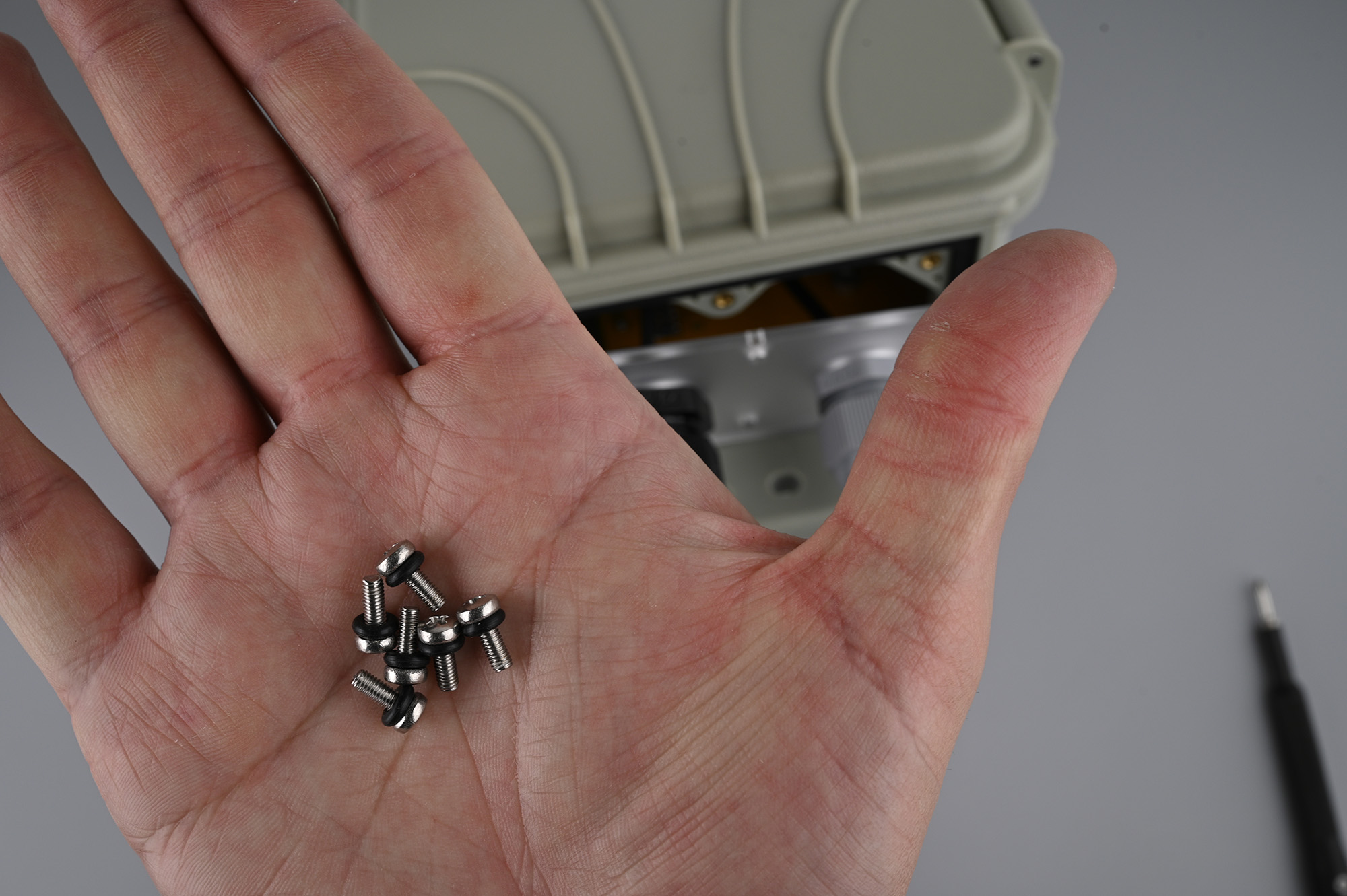
11. Add O-Rings to Screws
Open the packet marked ‘Cable Plate Screws’, and ensure that the included o-rings are fitted onto the cable plate screws. This provides optimal weather protection.
12. Check Gasket
Next, check that the gasket is pressed into the case groove to form a snug fit.
13. Screw in Cable Plate
Finally, screw your cable plate into place using the Cable Plate screws. It should be screwed in tightly, but be careful not to over-tighten the screws. The o-rings should be slightly compressed but not completely flattened.
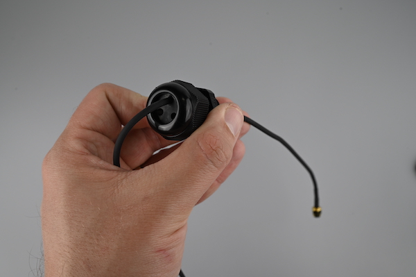
14. Adjust Cables and Tighten Front Cap
Loosen the front cap on the gland and adjust the length of your cables so that they reach their respective connectors on the FieldKit station without too much extra slack.
Tighten the front cap on the glands until they’re snug and the cables no longer slide.
15. Double Check Cables
Regardless of assembly order (either assembling the cable plate alongside module setup, or at the very end once you’re ready to deploy), be sure to follow each cable from the instrument to the module board to ensure that it is plugged into the right module board. It may be easier to run your finger along the cable to make sure you have the right one.
Optional: To improve water resistance, silicone can be used on the inserts to create a seal.
Set Up Modules
It’s now time to complete the final stages of setup before deployment.
Follow the instructions in the app to assemble your Sensor Packs, place them on the station in the bay of your choosing, ensuring the correct probe or instrument cluster is paired with the module board, and then (if needed) calibrate the sensors to set a baseline for accurate readings.
You may choose to assemble your cable plate at the same time or wait until the very end of station setup.
Plug in Sensor Packs to Activate Modules
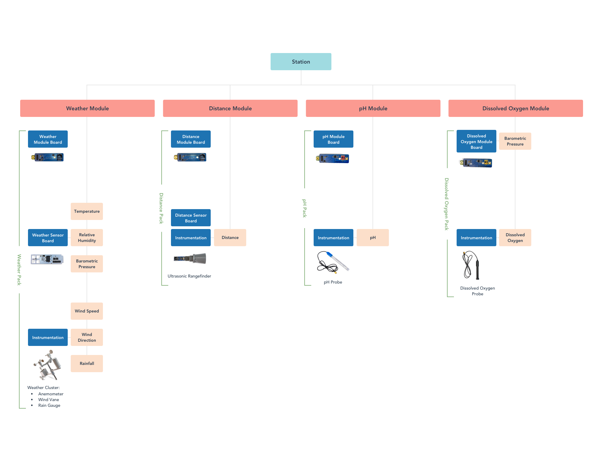
FieldKit Station data is organized into sensor modules. Modules group together sensors and their data according to distinct environmental factors, e.g. weather or pH. Each module contains data from multiple sensors, which are physically located at various points across the hardware (via circuit boards or instruments). The hardware itself is packaged together and sold in the form of products called Sensor Packs.
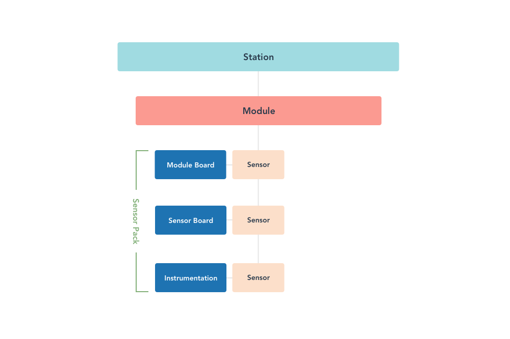
After purchasing your Sensor Pack, you assemble the physical parts and plug the associated Module Board into the Core. Now the module is ready to start collecting data. At this point, that module is activated, and data enters the station’s ecosystem as part of that module.
Example: You assemble your pH Pack and look at it on your desk. It’s cool but it’s just a pH Pack. But then you plug it into the Core. And hey, presto! It’s now a data-gathering pH Module.
Calibrate Sensors for Accurate Readings
What is Calibration?
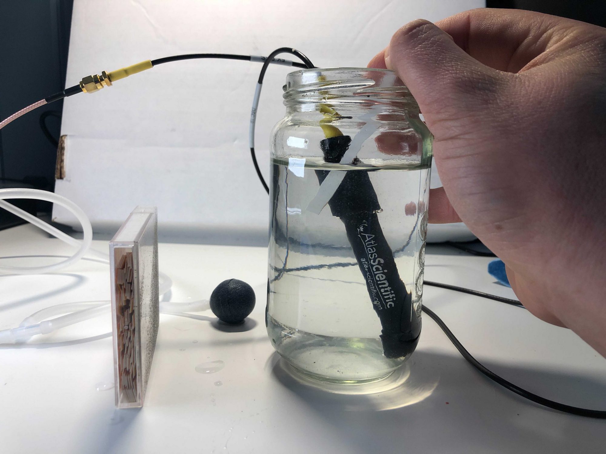
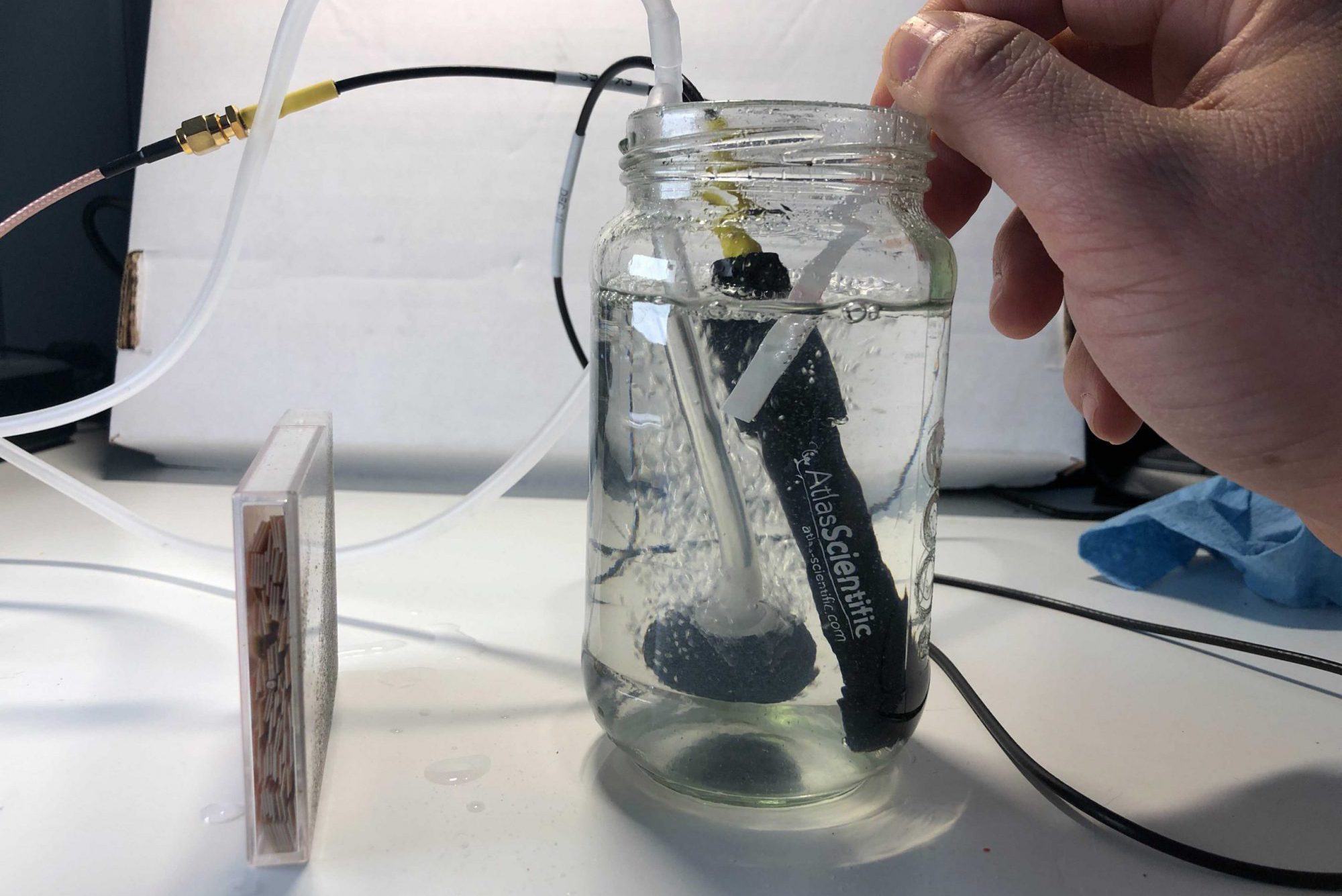
Calibration is essential for accurate data readings. Modern sensors and transmitters are electronic devices, and their behaviors may drift over time due to temperature, pressure or changes in ambient conditions, resulting in inaccurate readings. Therefore, calibration is necessary to correct a sensor’s baseline readings and needs to be done with all new sensors. Later on, you will likely need to recalibrate your FieldKit sensors at regular intervals to keep them accurate. Check your particular sensors for CAL ID decals to determine whether they have been calibrated in our lab and how frequently they require recalibration.
Before calibration, examine your module board and probe cable for a Calibration ID (CAL ID) decal. All probes and module pairs that have the same CAL ID printed on them have been calibrated together in the lab and will not require calibration before their initial use. Additionally, if you have multiple probes of the same type, take care to match the CAL ID number on the probe cable and the module board when setting up the station (see images below). Failure to do so may result in inaccurate data and a need to recalibrate.
How do I do it?
For calibration, you’ll need trusted calibration standards—read on for our recommendations. Standards come in a few different forms (see below). In all cases, you’ll use the readings that you get from your standards (the standard value) as a source of truth to correct the FieldKit sensors’ baseline readings (the sensor value).
The app will guide you through the process, which follows three main steps per sensor, done three times for each module in order to establish a three-point calibration:
1. Test using the following:
- FieldKit sensor
- External standard(s)
2. Enter the standard value into the app
3. Hit “calibrate.” This will record both the current sensor value and the standard value together, which allows us to later calibrate the sensor.
Calibration Standards
Calibration standards provide a source of truth to correct the FieldKit sensors’ baseline readings and can take the form of physical quantities, standard solutions, or measurement devices. There are two main methods of calibration, each using different types of standard.
Direct Calibration
This method corrects the FieldKit sensor’s baseline readings with trusted standard inputs, like solutions that have been reliably pre-mixed to a specific quantity, a calibrator that gives a known voltage, or a resistance substitution box that gives a known resistance.
Example: for pH you can use a pH 4.00 standard.
It’s called a direct calibration because you take the measurement with your FieldKit sensor directly from the value of the reliable external standard that is also the quantity (the bottle says “pH 4.00”).
Transfer Calibration
This method corrects the FieldKit sensor’s baseline readings with the readings of a separate measuring device that you already trust to be precise, known as your transfer standard. The same thing (what’s known as the transfer medium) is measured by your FieldKit sensor and the external measurement device at the same time.
Example: For water temperature, you can use boiling water and a standard thermometer.
It’s called a transfer calibration because the precision of measurement of the trusted device, or standard (e.g. the standard thermometer), is being transferred through simultaneous measurement of the same quantity (boiling water) to the thing being calibrated (the FieldKit sensor), which is referred to as the Device Under Test or DUT.
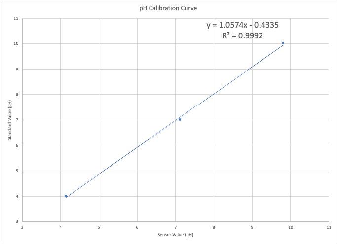
When doing a calibration, you’re actually doing two different tasks, one after the other. The first one is known as characterization, and it’s how you determine how the sensor is behaving relative to your standard. In our case, that involves taking a series of measurements, pairs of numbers we can represent like (x, y), where x is the value of the sensor, and y is the value of the standard. Next, we do some math to see if there’s a line that will go through all of these (x, y) pairs, and the function that makes that line on a graph is what’s known as our calibration function.
Which calibration standards do I need to source?
For calibrating your FieldKit sensors, we recommend the following or equivalents. Most of these can be sourced online, while others you can find around your home or workplace. If you expect to encounter numbers outside of these ranges in deployment, it’s fine to use other standards (e.g. for conductivity).
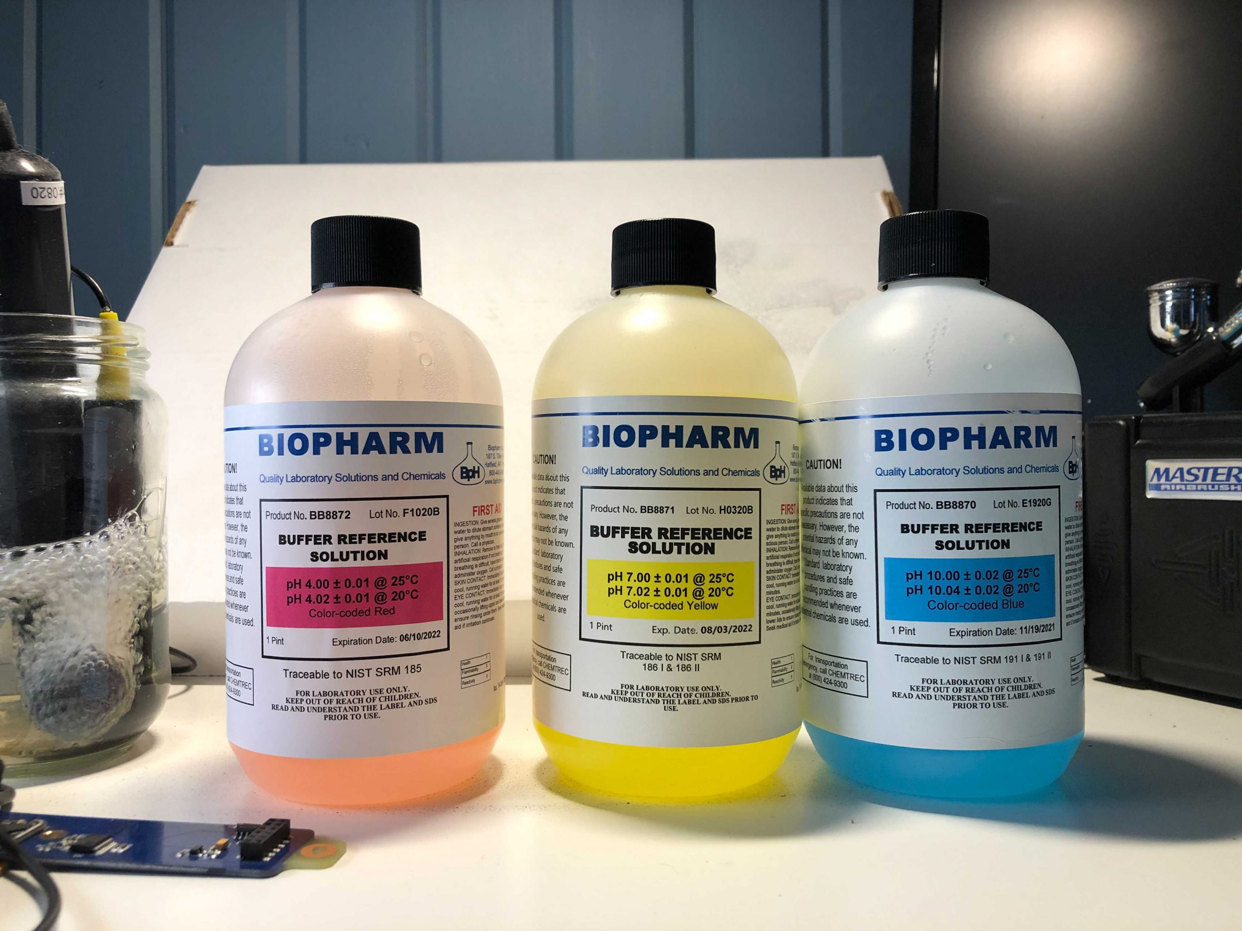
- pH: 4.00, 7.00, and 10.00 pH standard buffer solutions
- Electrical Conductivity: 84, 1413, and 12880 µS/cm conductivity standard solutions
- Temperature: ice water and boiling distilled water (0 and 100 °C, respectively)
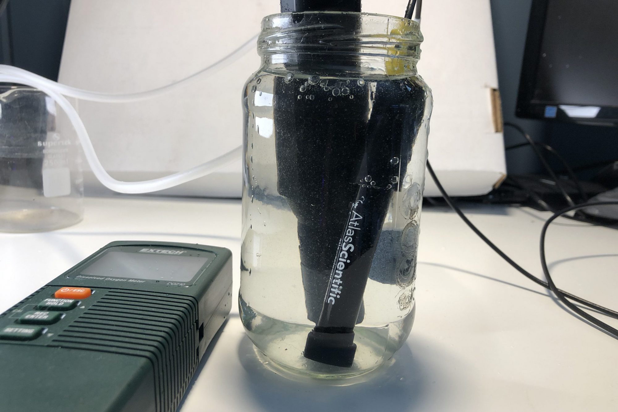
- Dissolved Oxygen: Extech DO600 Dissolved Oxygen meter or equivalent, such as an aquarium DO testing kit
How often do I need to calibrate my sensors?
We recommend, at minimum, recalibrating your sensors according to the following schedule:
- pH: every 3 months
- Dissolved Oxygen and ORP: every 6 months (also recondition the probes at this time)
- All other sensors: 1 year
Additionally, if you notice a significant, consistent drift in a certain direction outside of the above schedule, especially one that starts at an identifiable point in time (e.g. right after a big storm), that may be a sign that something has affected your sensor in the field and it’s time to bring it in for recalibration. To recalibrate your sensors, you can use the same process you used for the original sensor calibration, either via the FieldKit App or the Product Guide.
pH Module Setup
Assemble pH Pack
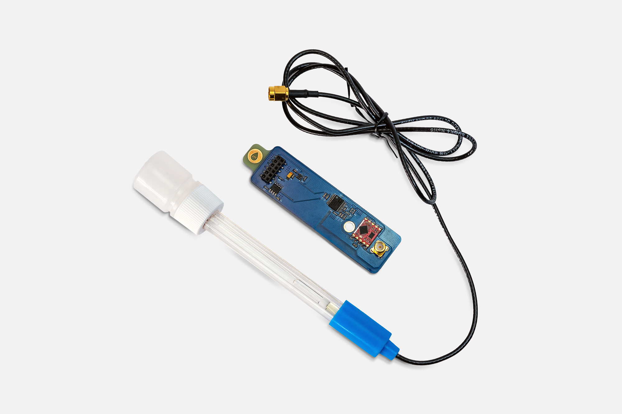
Your pH Pack consists of a pH Module Board and a pH Probe. The pH Pack components for FieldKit are color-coded red.
Before calibration, examine your module board and probe cable for a Calibration ID (CAL ID) decal. All probe and module pairs that have the same CAL ID printed on them have been calibrated together in the lab and will not require calibration before their initial use. Additionally, if you have multiple probes of the same type, take care to match the CAL ID number on the probe cable and the module board when setting up the station (see image below). Failure to do so may result in inaccurate data and a need to recalibrate.

1. Do you have everything?
Collect the pH Probe. The pH Module Board should already be attached to your station.
2. Attach to Station
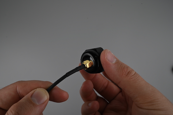
Screw the pH Probe cable into the pH Module Board.
3. Congratulations!
Your pH Module is now activated and ready for calibration.
The pH Probe has an end cap containing a buffer solution that helps to maintain the life of the probe. This end cap will need to be removed when using the probe. More information on working with the pH Probe, end cap and buffer solution can be found under Water Deployments.
Calibrate pH Sensors
Calibrate the sensors on your pH module for accurate data readings.
Measuring pH
pH is a logarithmic measure of free protons (or hydrogen ions) in a given solution. Chemically, it is expressed as -log([H+]), which is the negative base ten logarithm of the concentration of hydrogen. This is the molar concentration, essentially what fraction of 6.02*10^23 free protons exist in one liter of solution. That means that pH is measured in -log(mol/L), but it’s easier to just denote it with the leading symbol pH.
Three-point Calibration
During this calibration process, you’ll enter three separate and distinct calibration points that correlate with readings from an external standard. This will take the form of three pH standard solutions in order to make certain that the probe and module board are behaving in the way that we expect them to. All three of these standard solutions are known as buffers, which means that they can be concentrated or diluted by an appreciable amount before changing their pH. This means that pH buffers can be left out for a while without having to worry about their pH changing due to evaporation. These buffers are not toxic, and should be able to be rinsed down a drain when being disposed of (check the label of the buffer you’re using to be sure and follow the instructions listed).
While the order of buffers doesn’t strictly matter, we normally go from low to high and the following instructions will proceed in this order. Regardless, the app process will work in any order, so long as you’re entering your standard values to calibrate your actual probe readings at each point.
Equipment
- pH Pack
- Cup or other container
- 3 x pH standard solutions (we recommend pH 4.00, 7.00, and 10.00)
- De-ionized, distilled, or tap water
- Clean towel for drying probes in between standards

If you have older pH standards, you may need to replace them. If you’re not able to, or if you’re reusing standards for multiple calibrations, consider using a pH meter as a standard, such as the Extech PH100 or equivalent.
1. Do you have everything?
Make sure you have 3 different pH standard solutions. We recommend pH 4.00, 7.00, and 10.00. These instructions will proceed as if you are going from lowest to highest pH but the order in which you perform the calibration does not matter.
2. Calibration Point 1
First, you’ll put the probe in the first pH buffer.
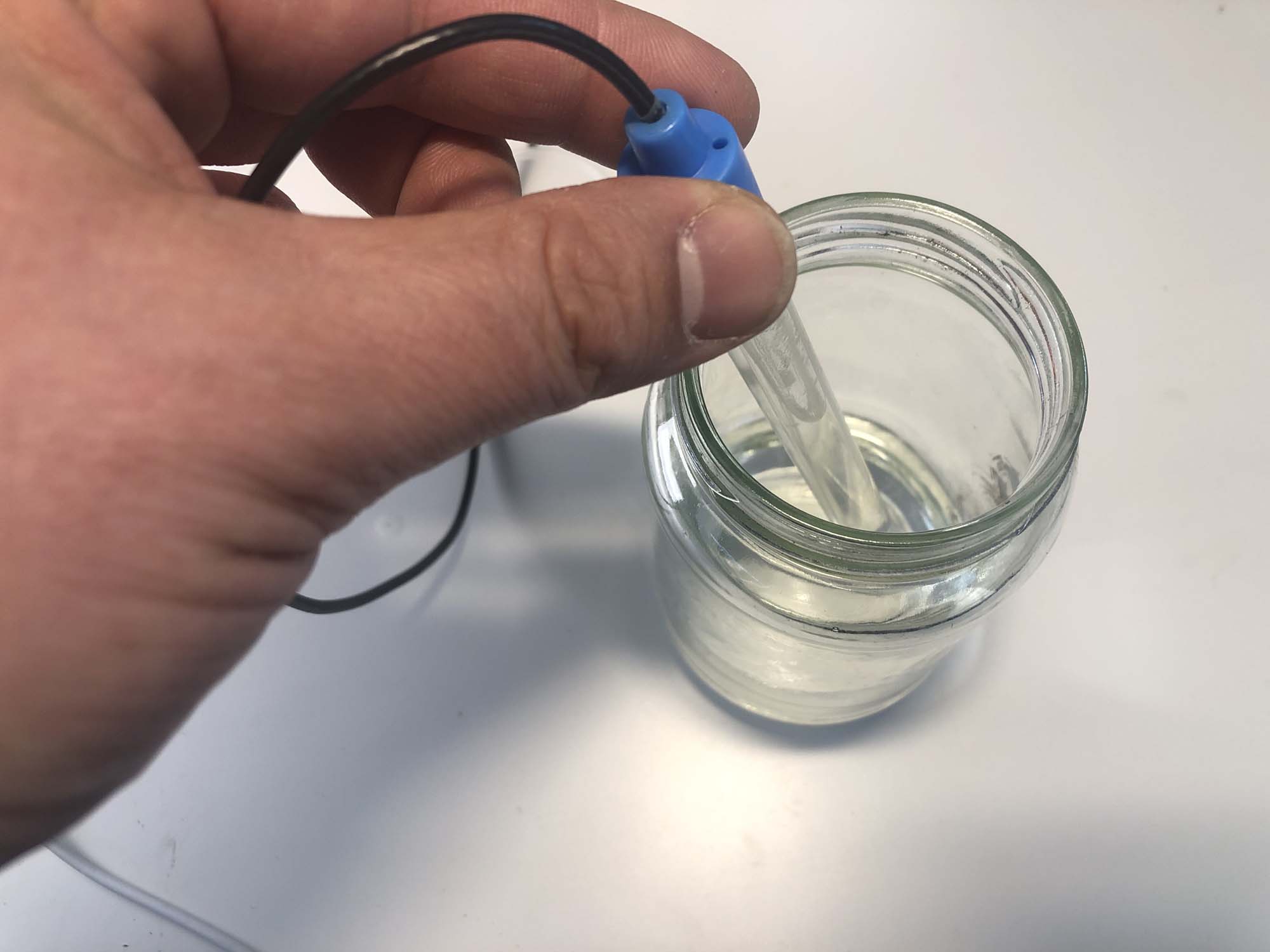
a) Insert pH Probe
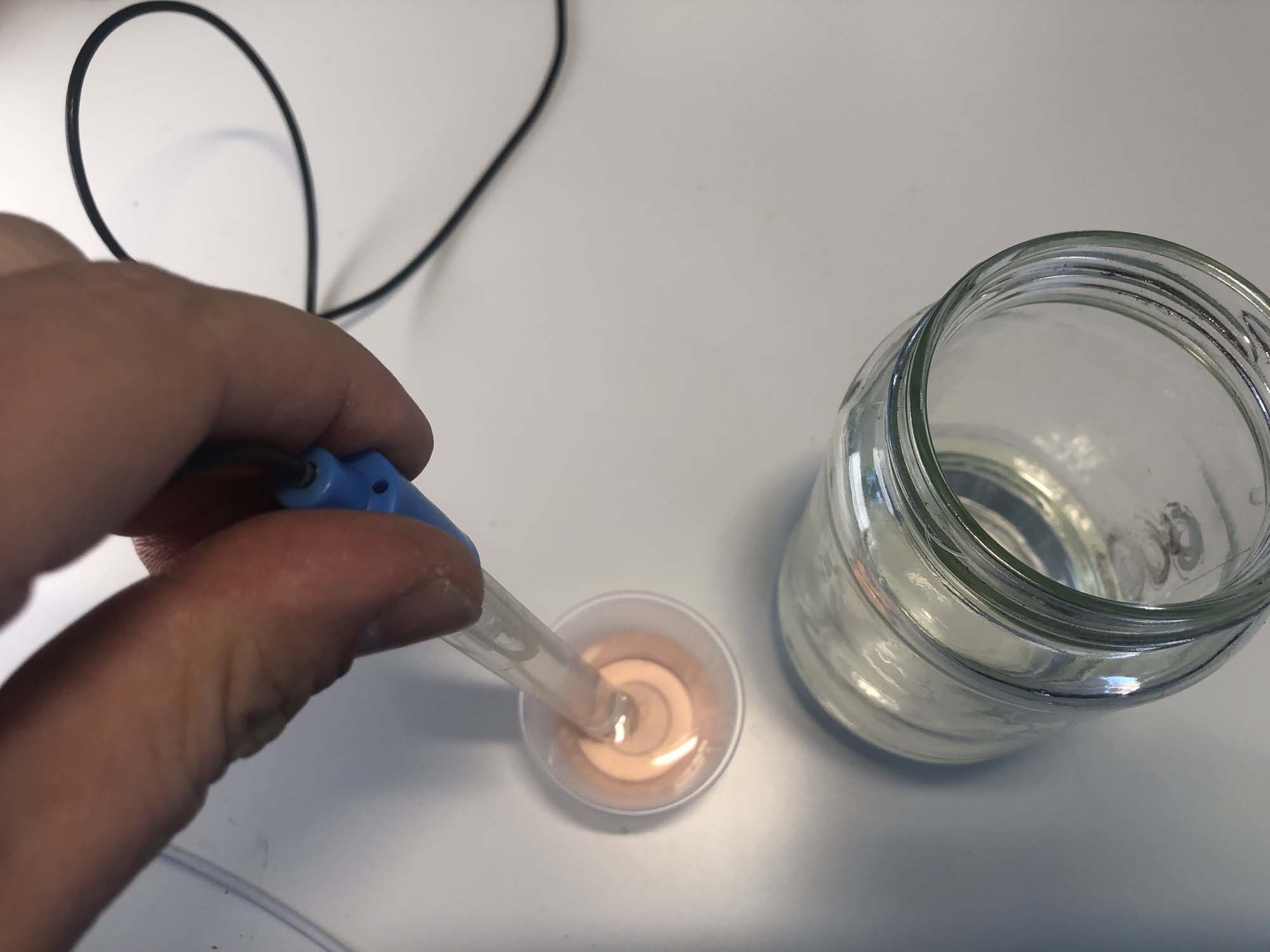
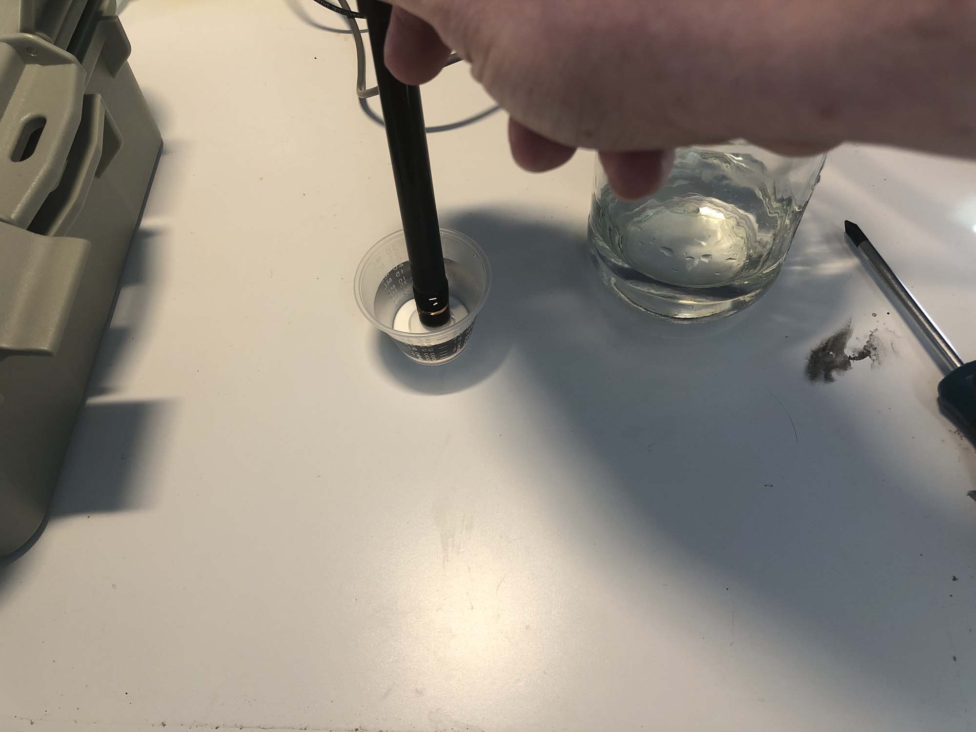
Insert the probe into a container with at least enough pH 4.00 standard solution to completely cover the glass and electrode portion sticking out of the plastic at the base of of the pH probe.
b) Enter Standard Value as Readings Stabilize
Allow time for the reading on the pH Probe to stabilize. In the app, the timer will count down. As you wait for the timer to count down, enter the value from the pH standard solution into the app field. Note: This field will be pre-populated with “pH 4.00”. If yours is different, you can edit what is displayed and should override it with the value of your pH standard solution.
c) Success
When the timer stops, press the “Calibrate” button. This will record both the current sensor value and the standard value together, which allows us to later calibrate the sensor.
3. Calibration Point 2
Then, you’ll put the probe in the second pH buffer.
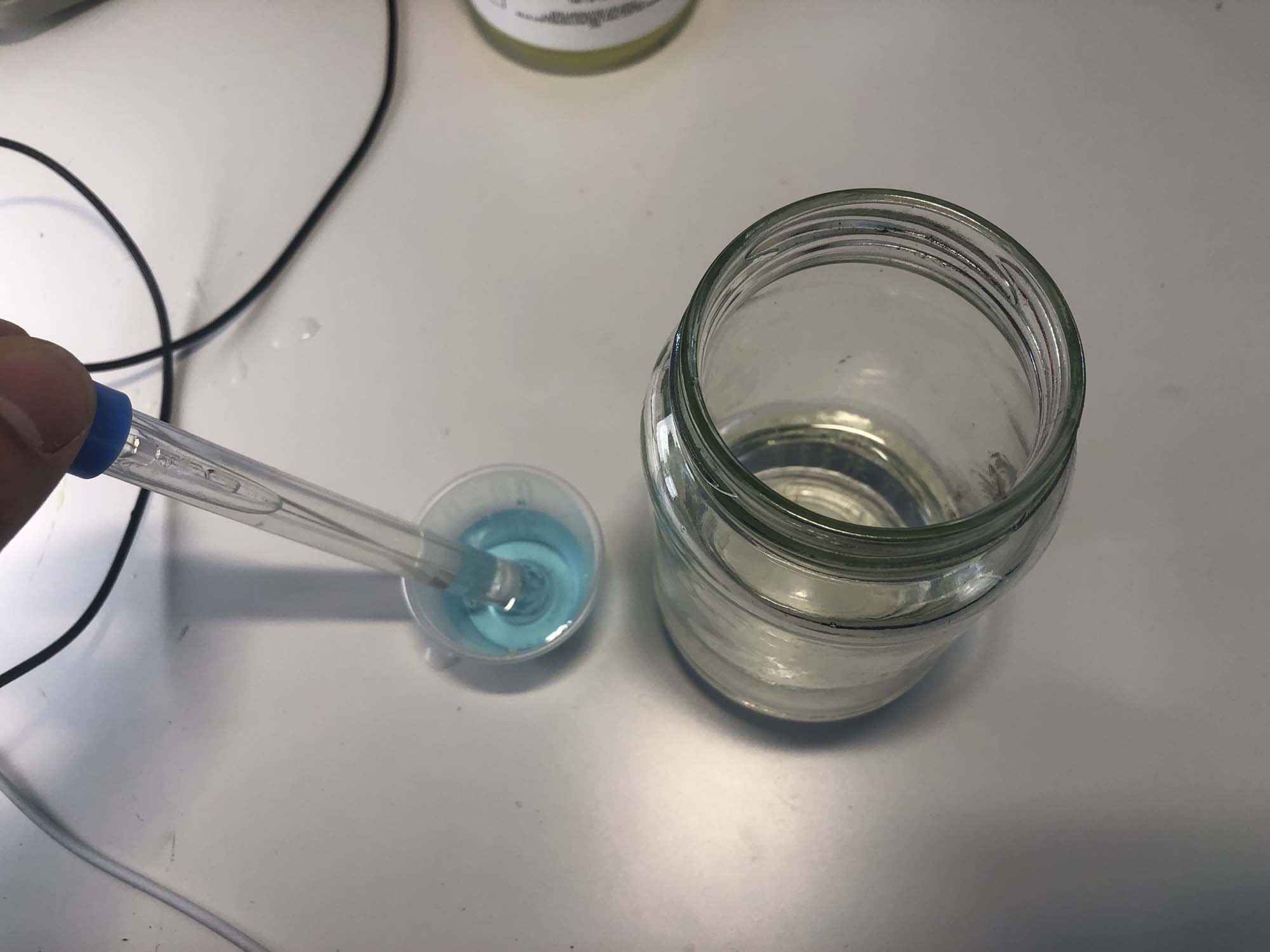
a) Rinse and Dry Probe
Rinse off the probe end with water. You can either use a bottle with a nozzle for this, or just dip the probe end into water (do not re-use the water between calibration points). Dry using your clean towel.
b) Insert pH Probe
Place the pH Probe into the container with at least enough pH 7.00 standard solution to completely cover the glass and electrode portion sticking out of the plastic at the base of of the pH probe.
c) Enter Standard Value as Readings Stabilize
Allow time for the reading on the pH Probe to stabilize. In the app, the timer will count down. As you wait for the timer to count down, enter the value from the pH standard solution into the app field. Note: This field will be pre-populated with “pH 7.00”. If yours is different, you can edit what is displayed and should override it with the value of your pH standard solution.
d) Success
When the timer stops, hit the “Calibrate” button. This will record both the current sensor value and the standard value together, which allows us to later calibrate the sensor.
4. Calibration Point 3
Finally, you’ll put the probe in the third pH buffer.
a) Rinse and Dry Probe
Rinse off the probe end with water. You can either use a bottle with a nozzle for this, or just dip the probe end into water (do not re-use the water between calibration points). Dry using your clean towel.
b) Insert pH Probe
Place the pH Probe into the container with at least enough pH 10.00 standard solution to completely cover the glass and electrode portion sticking out of the plastic at the base of the pH probe.
c) Enter Standard Value as Readings Stabilize
Allow time for the reading on the pH Probe to stabilize. In the app, the timer will count down. As you wait for the timer to count down, enter the value from the pH standard solution into the app field. Note: This field will be pre-populated with “pH 10.00”. If yours is different, you can edit what is displayed and should override it with the value of your pH standard solution.
d) Success
When the timer stops, hit the “Calibrate” button. This will record both the current sensor value and the standard value together, which allows us to complete calibration.
5. Congratulations!
You’ve now completed your pH calibration.
Water Temperature Module Setup
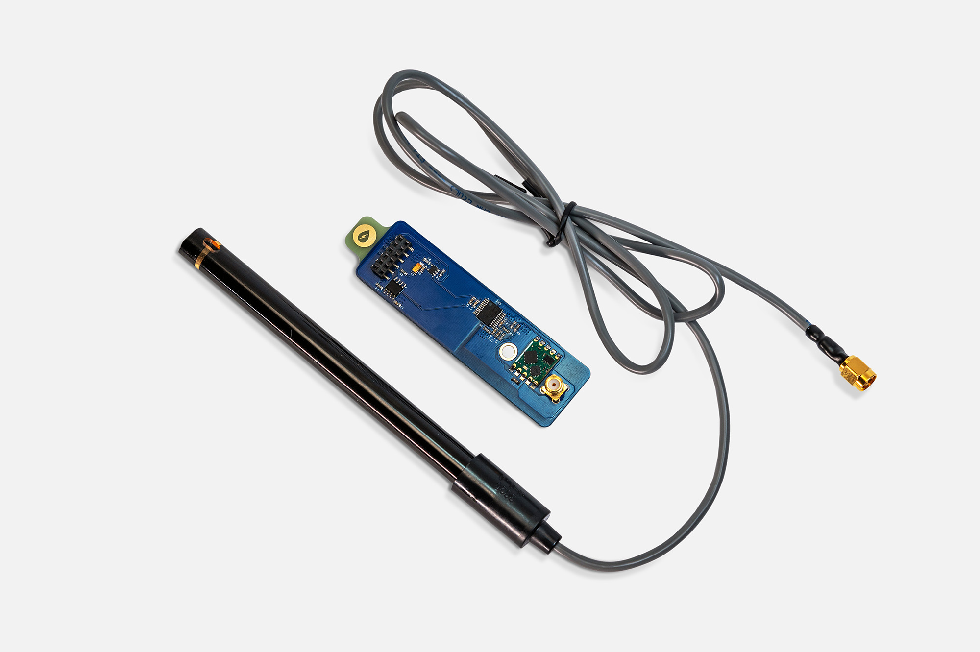
Assemble Water Temperature Pack
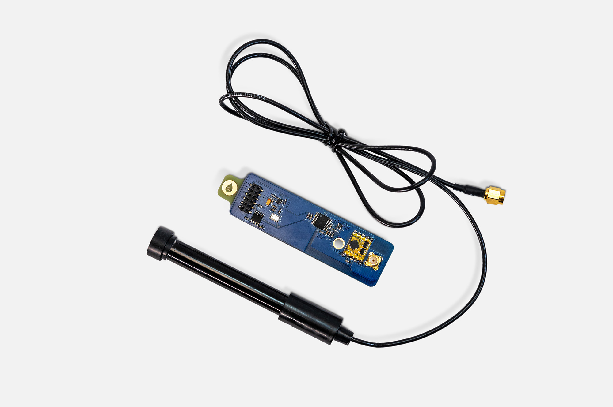
Your Water Temperature Pack consists of a Water Temperature Module Board and a Water Temperature Probe. The Water Temperature Pack components for FieldKit are color-coded black.
Before calibration, examine your module board and probe cable for a Calibration ID (CAL ID) decal. All probe and module pairs that have the same CAL ID printed on them have been calibrated together in the lab and will not require calibration before their initial use. Additionally, if you have multiple probes of the same type, take care to match the CAL ID number on the probe cable and the module board when setting up the station (see image below). Failure to do so may result in inaccurate data and a need to recalibrate.
1. Do you have everything?
Collect the Water Temperature Probe. The Water Temperature Module Board should already be attached to your station.
2. Attach to Station
Screw the Water Temperature Probe cable into the Water Temperature Module Board.
3. Congratulations!
Your Water Temperature Module is now activated and ready for calibration.
Calibrate Water Temperature Sensors
Calibrate the sensors on your Water Temperature module for accurate data readings.
Measuring Temperature
Temperature is measured in degrees Celsius (°C). In this case, we’re using a thermistor, which is a resistive device that changes the amount of electric current it will allow through based on the temperature at which it is operating. These have to operate in a narrow band of electric currents: too much, and you risk the thermistor self-heating and creating a measurement error; too little, and the electrical noise overwhelms our temperature signal. We calibrate to make certain that the probe and module board are behaving as we expect them to in this case, and correct if they’re not.
Three-Point Transfer Calibration
During this transfer calibration process, you’ll enter three separate calibration and distinct points and check that they correlate with readings from an external standard. This will take the form of ice water, room temperature, and boiling water in order to make certain that the probe and module board are behaving in the way that we expect them to.
Equipment
- Temperature Pack
- De-ionized, distilled, or tap water (any will do)
- Ice
- Pot, tea kettle, or other device for boiling water
- Cup, glass or mug, capable of withstanding boiling temperatures
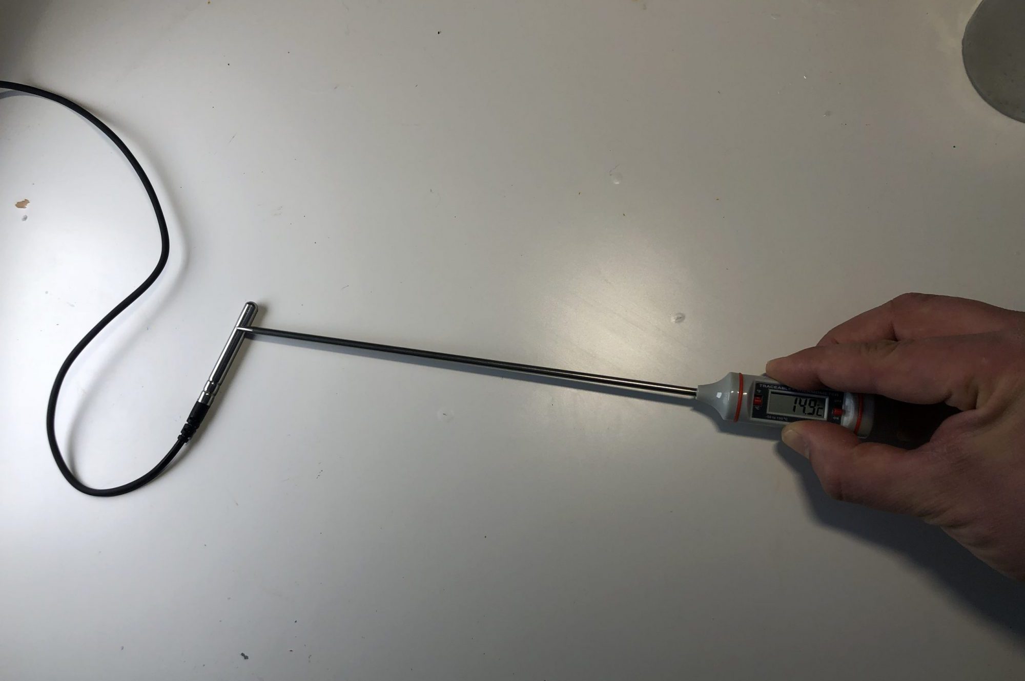
- Standard thermometer

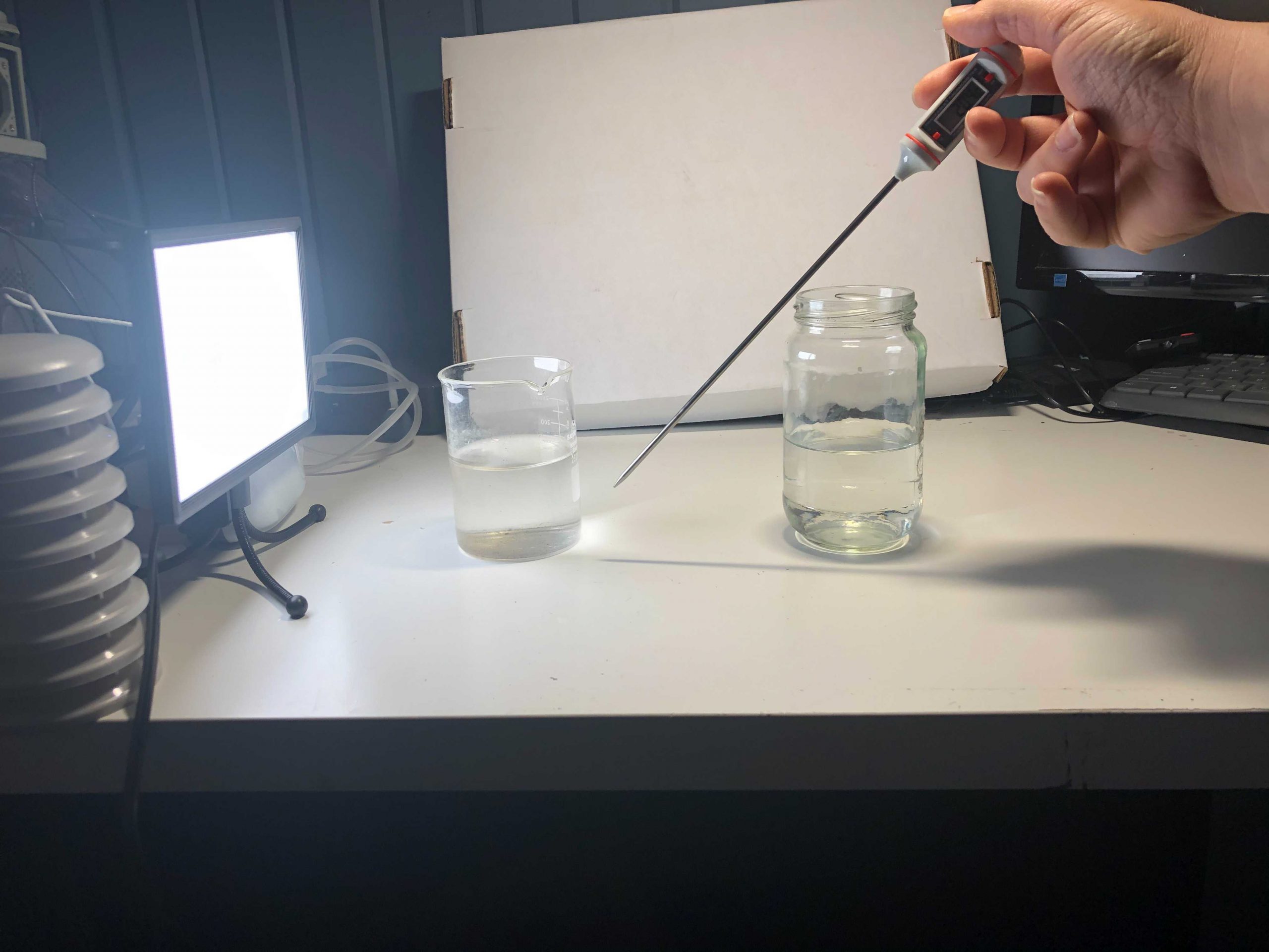
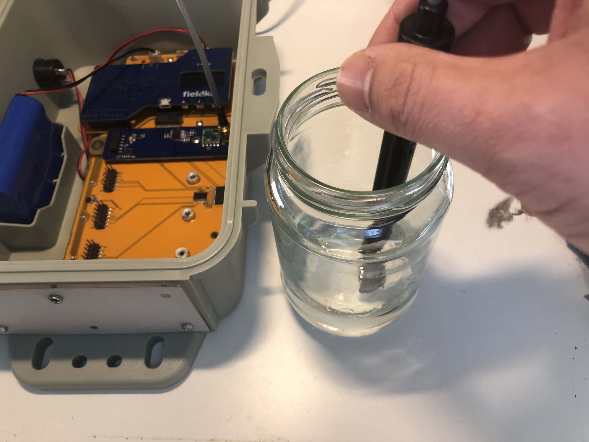
1. Do you have everything?
Make sure you have three temperature sources and a standard thermometer.
We recommend using the following sources in this order: a container of ice water (0°C), room temperature water, and a container of boiling water (100°C).
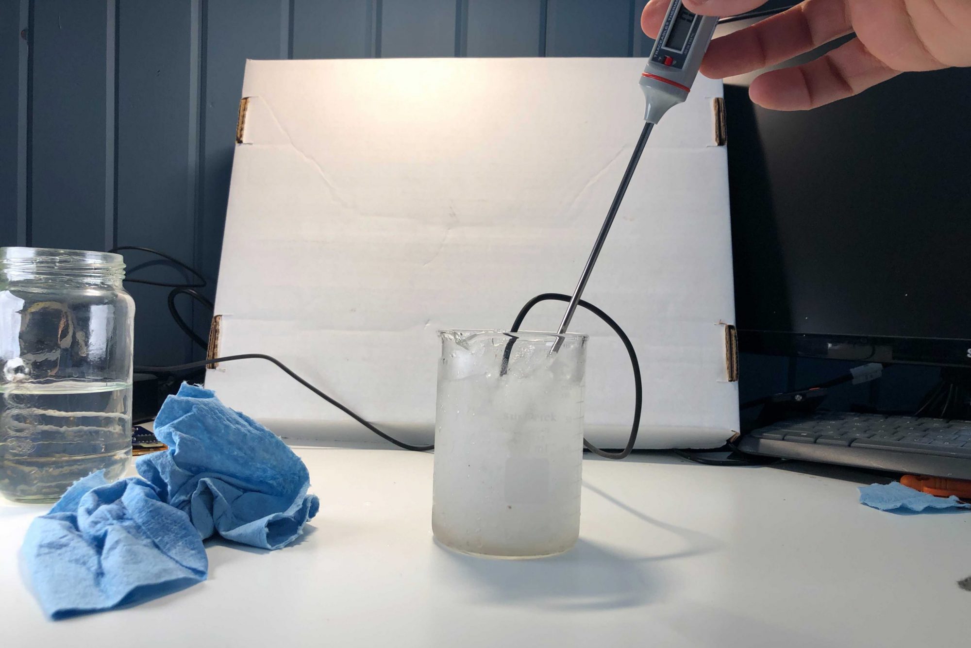
2. Low-Point Calibration
First, you’ll measure a low temperature. Usually we’d use a physical constant. In this case it’s the triple point of water, 0°C, the temperature at which water can exist as a solid, a liquid, and a gas.
a) Mix Some Ice Water
Place some ice cubes into a container of water. Thoroughly mix it together.
b) Insert Water Temperature Probe and Standard Thermometer
Place the Water Temperature Probe and standard thermometer into the cup of ice water that’s been thoroughly mixed.
c) Enter Standard Value as Readings Stabilize
Allow time for the readings on the standard thermometer to stabilize. In the app, the timer will count down. As you wait for the timer to count down, enter the value from the standard thermometer into the app field. Note: This field will be pre-populated with “0°C”. If yours is different, you can edit what is displayed and should override it with the value displaying on your thermometer.
d) Success
When the timer stops, hit the “Calibrate” button. This will record both the current sensor value and the standard value together, which allows us to later calibrate the sensor.
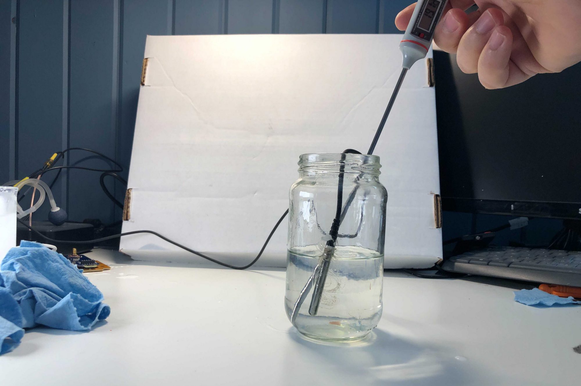
3. Mid-Point Calibration
Then, you’ll measure an arbitrary temperature, probably between 0 and 100 °C. Usually ambient or room temperature is used for this.
a) Dry Off Probe and Standard Thermometer
Dry off the Water Temperature Probe and standard thermometer.
b) Place Water Temperature Probe and Standard Thermometer
Place the standard thermometer and Water Temperature Probe in contact with one another in a container of room temperature water.
c) Enter Standard Value as Readings Stabilize
Allow time for the readings on the standard thermometer to stabilize. In the app, the timer will count down. As you wait for the timer to count down, enter the value from the standard thermometer into the app field. Note: This field will be pre-populated with “20°C”. If yours is different, you can edit what is displayed and should override it with the value displaying on your thermometer.
d) Success
When the timer stops, hit the “Calibrate” button. This will record both the current sensor value and the standard value together, which allows us to later calibrate the sensor.
4. High-Point Calibration
Finally, you’ll use the boiling point of water as your high point for calibration. This will vary with your altitude and barometric pressure, so the 100 °C that you’d get under 100 kPa at sea level isn’t necessarily what you’ll see. Thus make certain to enter the temperature from your standard thermometer into the calibration temperature field in the app.
a) Boil Water
Boil some water and pour it into a container that is capable of withstanding boiling temperatures.
b) Dry Off Probe and Standard Thermometer
Dry off the Water Temperature Probe and standard thermometer.
c) Insert Water Temperature Probe and Standard Thermometer
Place the Water Temperature Probe and standard thermometer into the container of boiling water.
d) Enter Standard Value as Readings Stabilize
Allow time for the readings on the standard thermometer to stabilize. In the app, the timer will count down. As you wait for the timer to count down, enter the value from the standard thermometer into the app field. Note: This field will be pre-populated with “100°C”. If yours is different, you can edit what is displayed and should override it with the value displaying on your thermometer.
e) Success
When the timer stops, hit the “Calibrate” button. This will record both the current sensor value and the standard value together, which allows us to complete calibration.
5. Congratulations!
You’ve now completed your water temperature calibration.
Conductivity Module Setup
Assemble Conductivity Pack
Your Conductivity Pack consists of a Conductivity Module Board and a Conductivity Probe. The Conductivity Pack components for FieldKit are color-coded green.
Before calibration, examine your module board and probe cable for a Calibration ID (CAL ID) decal. All probe and module pairs that have the same CAL ID printed on them have been calibrated together in the lab and will not require calibration before their initial use. Additionally, if you have multiple probes of the same type, take care to match the CAL ID number on the probe cable and the module board when setting up the station (see image below). Failure to do so may result in inaccurate data and a need to recalibrate.
1. Do you have everything?
Collect the Conductivity Probe. The Conductivity Module Board should already be attached to your station.
2. Attach to station
Screw the Conductivity Probe cable into the Conductivity Module Board.
3. Congratulations!
Your Conductivity Module is now activated and ready for calibration.
Calibrate Conductivity Sensors
Calibrate the sensors on your Conductivity module for accurate data readings.
Measuring Conductivity
Conductivity is measured in Microsiemens Per Centimeter (µS/cm). This means measuring the amount of electrical current that flows across a gap between two graphite electrodes in the probe, along with the voltage drop across them, and dividing one by the other, and by the distance between the two electrodes. Calibration is necessary because mineral deposits can form on the electrodes and other factors can interfere with the measurement. Unlike the buffer solutions used for pH calibration, the standard solutions used in this calibration are extremely sensitive to concentration or dilution, and so need to be protected from evaporation by being left in sealed containers when not in use. As a general practice, it is best to replace the solution in between each calibration. The solution is essentially salt water and can easily be disposed of by dumping it down the drain in the small quantities used in this calibration (but we recommend you check the label of your solution for further instructions).
Three-Point Calibration
Make sure you have three different conductivity standard solutions. We recommend 1,000, 10,000, and 100,000 µS/cm if this is appropriate for the environment you will be measuring.
During this transfer calibration process, you’ll enter three separate and distinct calibration points and check that they correlate with readings from an external standard. This will take the form of three Conductivity standard solutions in order to make certain that the probe and module board are behaving in the way that we expect them to.
Equipment
- Conductivity Pack
- Container
- 3 x conductivity standard solutions (we recommend 1,000, 10,000, and 100,000 µS/cm standards)
- De-ionized, distilled, or tap water
- Clean towel for drying probes in between standards

If you have older conductivity standards, you may need to replace them. If you’re not able to, or if you’re reusing standards for multiple calibrations, consider using a conductivity meter as a standard, such as the Extech EC400 or equivalent.
1. Do you have everything?
Make sure you have three different conductivity standard solutions. We recommend 1,000, 10,000, and 100,000 µS/cm. These instructions will proceed as if you are going from lowest to highest concentration of salt, but the order in which you perform the calibration does not matter.
2. Calibration Point 1
First, you’ll put the Conductivity Probe into the lowest conductivity solution, the one with the least salt dissolved in it, and measure what that conductivity is so you can compare it with the standard’s expected value.
a) Insert Conductivity Probe
Place the Conductivity probe into a container with at least enough 1,000 µS/cm standard solution to completely cover the hole near the end of the probe.
b) Enter Standard Value as Readings Stabilize
Allow time for the reading on the Conductivity probe to stabilize. In the app, the timer will count down. As you wait for the timer to count down, enter the value from the Conductivity standard solution into the app field. Note: This field will be pre-populated with “1,000 µS/cm”. If yours is different, you can edit what is displayed and should override it with your conductivity standard solution value.
c) Success
When the timer stops, hit the “Calibrate” button. This will record both the current sensor value and the standard value together, which allows us to later calibrate the sensor.
3. Calibration Point 2
Then, you’ll clean off the probe and put it in the second solution.
a) Rinse and Dry Probe
Rinse off the probe end with water. You can either use a bottle with a nozzle for this, or just dip the probe end into water (do not re-use the water between calibration points). Dry using your clean towel.
b) Insert Conductivity Probe
Place the Conductivity probe into a container with at least enough 10,000 µS/cm standard solution to completely cover the hole near the end of the probe.
c) Enter Standard Value as Readings Stabilize
Allow time for the reading on the Conductivity probe to stabilize. In the app, the timer will count down. As you wait for the timer to count down, enter the value from the Conductivity standard solution into the app field. Note: This field will be pre-populated with “10,000 µS/cm”. If yours is different, you can edit what is displayed and should override it with your conductivity standard solution value.
d) Success
When the timer stops, hit the “Calibrate” button. This will record both the current sensor value and the standard value together, which allows us to later calibrate the sensor.
4. Calibration Point 3
Finally, you’ll clean off the probe and put it in the highest conductivity solution.
a) Rinse and Dry Probe
Rinse off the probe end with water. You can either use a bottle with a nozzle for this, or just dip the probe end into water (do not re-use the water between calibration points). Dry using your clean towel.
b) Insert Conductivity Probe
Place the Conductivity probe into a container with at least enough 100,000 µS/cm standard solution to completely cover the hole near the end of the probe.
c) Enter Standard Value as Readings Stabilize
Allow time for the reading on the Conductivity probe to stabilize. In the app, the timer will count down. As you wait for the timer to count down, enter the value from the Conductivity standard solution into the app field. Note: This field will be pre-populated with “100,000 µS/cm”. If yours is different, you can edit what is displayed and should override it with your conductivity standard solution value.
d) Success
When the timer stops, hit the “Calibrate” button. This will record both the current sensor value and the standard value together, which allows us to complete calibration.
5. Congratulations!
You’ve now completed your conductivity calibration.
Dissolved Oxygen Module Setup
Assemble Dissolved Oxygen Pack
Your Dissolved Oxygen Pack consists of a Dissolved Oxygen Module Board and a Dissolved Oxygen Probe. The Dissolved Oxygen Pack components for FieldKit are color-coded yellow.
Before calibration, examine your module board and probe cable for a Calibration ID (CAL ID) decal. All probe and module pairs that have the same CAL ID printed on them have been calibrated together in the lab and will not require calibration before their initial use. Additionally, if you have multiple probes of the same type, take care to match the CAL ID number on the probe cable and the module board when setting up the station (see image below). Failure to do so may result in inaccurate data and a need to recalibrate.
1. Do you have everything?
Collect the Dissolved Oxygen Probe. The Dissolved Oxygen Module Board should already be attached to your station.
2. Attach to station
Screw the Dissolved Oxygen Probe cable into the Dissolved Oxygen Module Board.
3. Congratulations!
Your Dissolved Oxygen Module is now activated and ready for calibration.
Dissolved Oxygen probes require reconditioning every 3-6 months to maintain accuracy. For more information on reconditioning your Dissolved Oxygen probe, please read this item from our FAQ.
Calibrate Dissolved Oxygen Sensors
Calibrate the sensors on your Dissolved Oxygen module for accurate data readings.
Measuring Dissolved Oxygen
Dissolved Oxygen is measured in percent saturation (%). Dissolved oxygen measurements come from what’s essentially a tiny battery made from a concentrated salt and water solution and a porous plastic membrane, along with two metal electrodes. Since any of those parts of the probe can get dirty, or otherwise damaged, we need to calibrate the probe and module board to correct for any errors.
Double-check that your Dissolved Oxygen meter is measuring percent saturation (%), as many simply calculate the percentage of oxygen relative to the maximum amount that can be dissolved in water at a given temperature. This will not work without further calculation to convert to %, as that is the default unit used by FieldKit.
Three-point Transfer Calibration
Make sure you have a container of water, an aquarium air pump, tubing and airstone, and a standard Dissolved Oxygen meter or test kit.
During this transfer calibration process, you’ll enter 3 separate and distinct calibration points and check that they correlate with readings from an external standard. This will take the form of a Dissolved Oxygen meter or an aquarium maintenance test kit in order to make certain that the probe and module board are behaving in the way that we expect them to.
Since this calibration is being done with two measuring devices, it is called a transfer calibration, meaning that the precision of measurement of the trusted device, or standard, is being transferred through simultaneous measurement of the same quantity to the thing being calibrated, what’s referred to as the Device Under Test, or DUT.
Equipment
- Dissolved Oxygen Pack
- Container of water
- Aquarium air pump, tubing, and airstone
- Standard Dissolved Oxygen meter or test kit (like those used for aquarium maintenance testing)
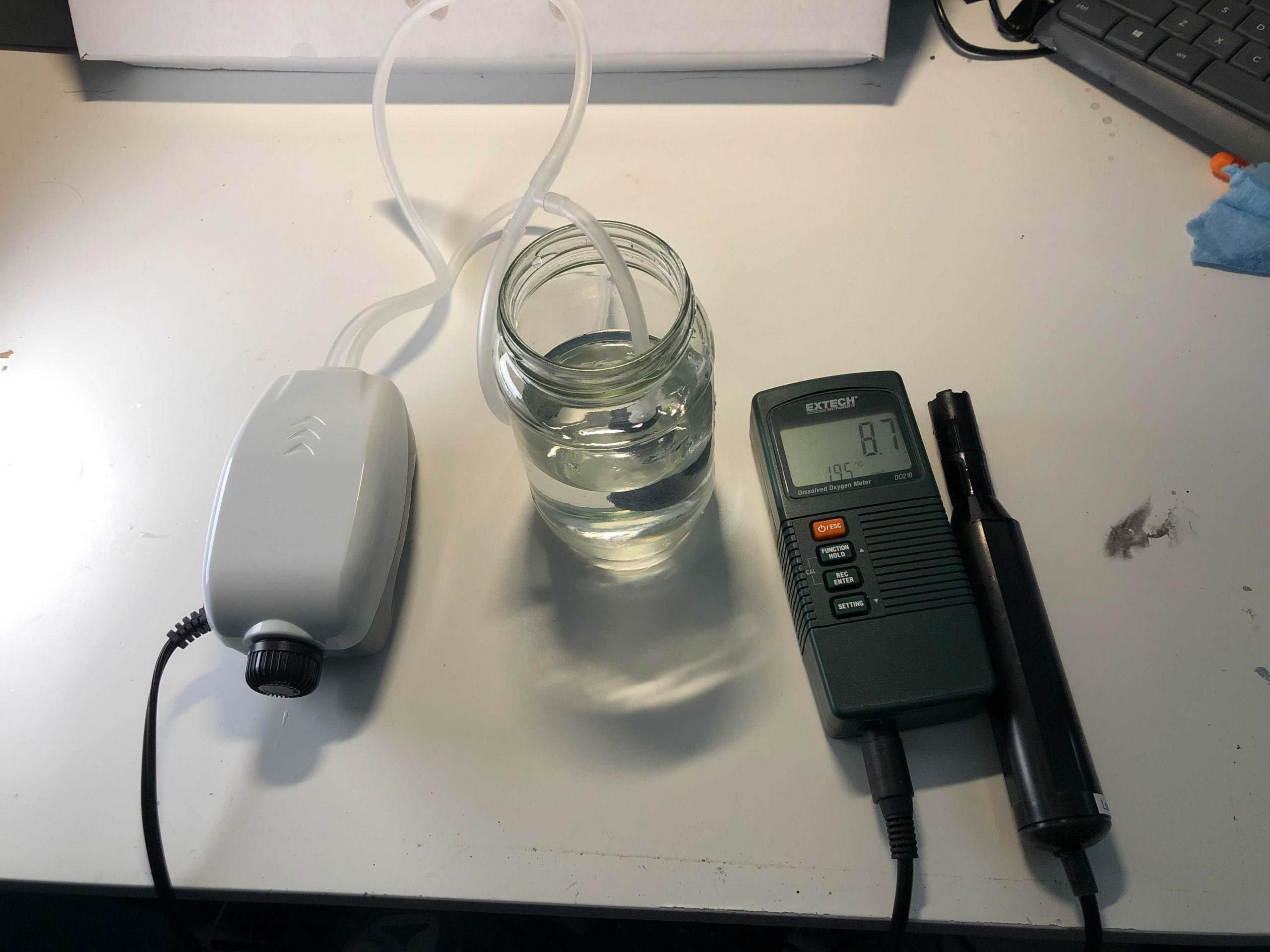
Option 1: Dissolved Oxygen Meter
1. Do you have everything?
Gather together a container of water, an aquarium air pump, tubing and airstone, and a standard Dissolved Oxygen meter.
2. Calibration Point 1
First, you’ll get a baseline reading of the amount of oxygen dissolved in the water that you’re using for the calibration.
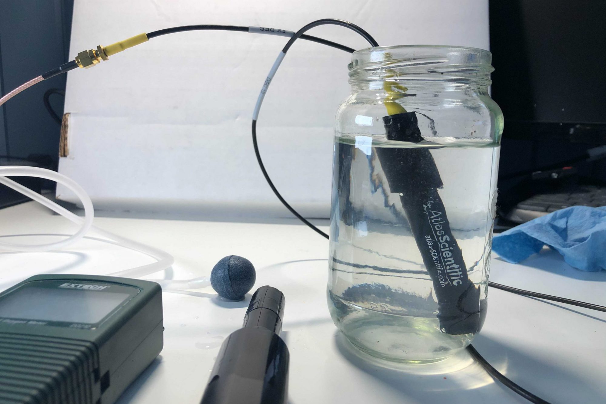
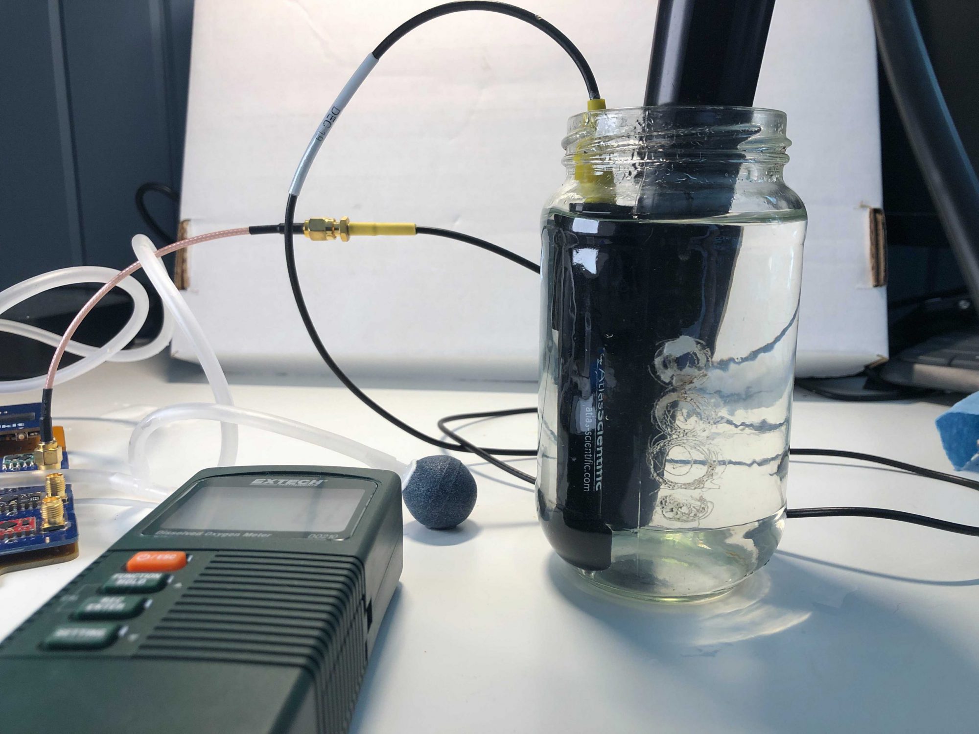
a) Insert Dissolved Oxygen Probe
Place the Dissolved Oxygen Probe in a container of water with your standard dissolved oxygen meter probe.
b) Enter Standard Value as Readings Stabilize
Allow time for the reading on the Dissolved Oxygen probe to stabilize. In the app, the timer will count down. As you wait for the timer to count down, enter the reading from the Dissolved Oxygen meter into the app field. Note: This field will be pre-populated with “5%”. If yours is different, you can edit what is displayed and should override it with the Dissolved Oxygen meter’s reading.
c) Success
When the timer stops, hit the “Calibrate” button. This will record both the current sensor value and the standard value together, which allows us to later calibrate the sensor.
3. Calibration Point 2
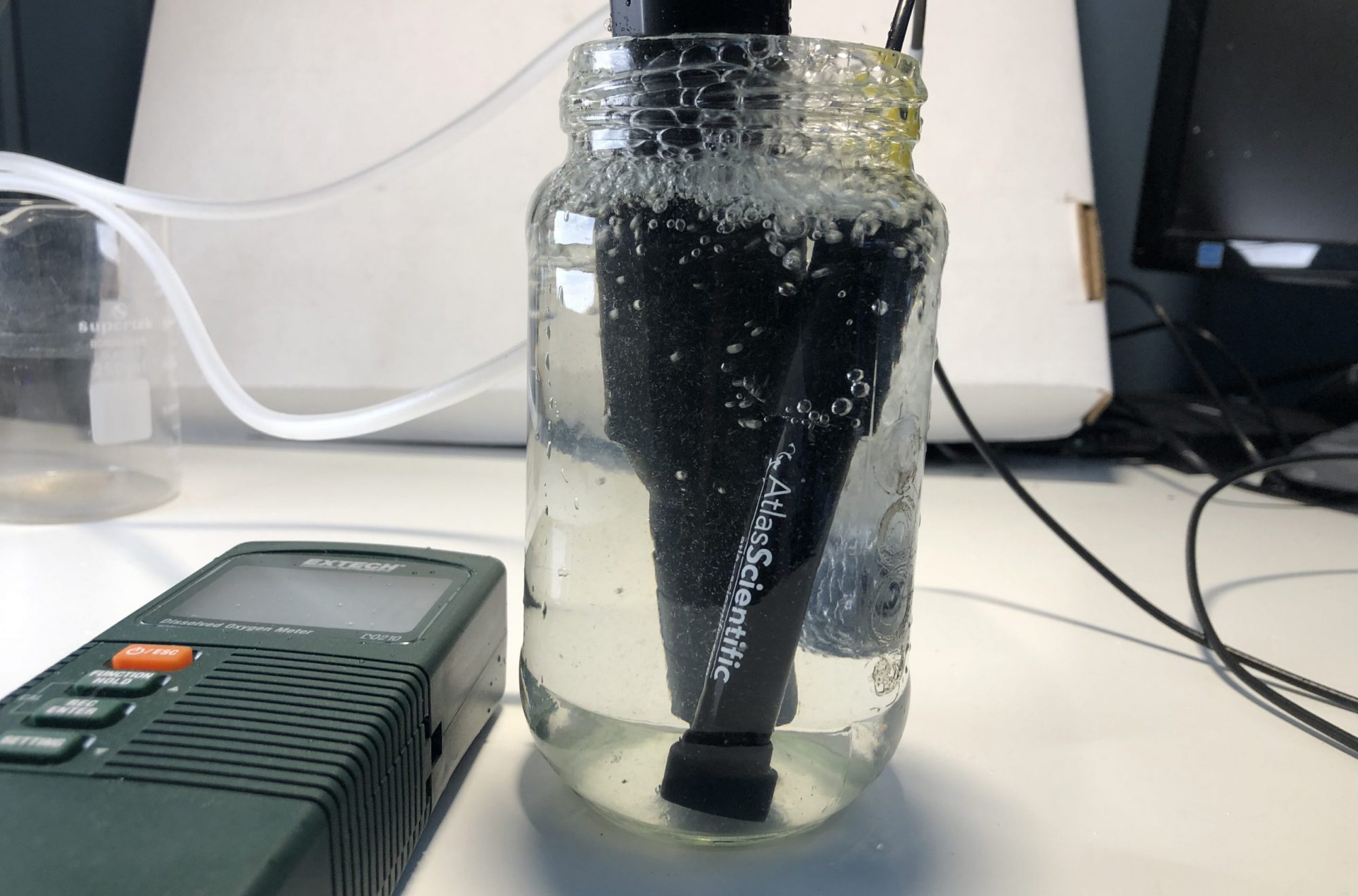
Then, you’ll get some oxygen dissolved in the water using a bubbler and measure its concentration.
a) Add the Airstone
Place the aquarium pump air stone into the container alongside the Dissolved Oxygen Probe and your standard meter.
b) Turn the Air Pump to Low for 3 Mins
Turn the air pump to low for three minutes.
c) Turn off the Pump
Turn off the pump.
d) Enter Standard Value as Readings Stabilize
Allow time for the reading on the Dissolved Oxygen probe to stabilize. In the app, the timer will count down. As you wait for the timer to count down, enter the reading from the Dissolved Oxygen meter into the app field. Note: This field will be pre-populated with “7.5%”. If yours is different, you can edit what is displayed and should override it with the Dissolved Oxygen meter’s reading.
e) Success
When the timer stops, hit the “Calibrate” button. This will record both the current sensor value and the standard value together, which allows us to later calibrate the sensor.
4. Calibration Point 3
Finally, you’ll attempt to saturate the water with as much oxygen as it can hold to calibrate the upper end of the probe’s range.
a) Keep Everything in the Container
Leave the aquarium pump air stone, Dissolved Oxygen Probe and your standard meter in the container.
b) Turn the Air Pump to High for 3 Mins
Turn the air pump to high for three minutes.
c) Turn off the Pump
Turn off the pump.
d) Enter Standard Value as Readings Stabilize
Allow time for the reading on the Dissolved Oxygen probe to stabilize. In the app, the timer will count down. As you wait for the timer to count down, enter the reading from the Dissolved Oxygen meter into the app field. Note: This field will be pre-populated with “9%”.If yours is different, you can edit what is displayed and should override it with the Dissolved Oxygen meter’s reading.
e) Success
When the timer stops, hit the “Calibrate” button. This will record both the current sensor value and the standard value together, which allows us to complete calibration.
5. Congratulations!
You’ve now completed your dissolved oxygen calibration.
Option 2: Aquarium Maintenance Test Kit

1. Do you have everything?
Gather together a container of water, an aquarium air pump, tubing and airstone, and an aquarium test kit.
2. Calibration Point 1
First, you’ll get a baseline reading of the amount of oxygen dissolved in the water that you’re using for the calibration.
a) Insert Dissolved Oxygen Probe
Place the Dissolved Oxygen Probe in a container of water.
b) Follow Test Kit Instructions
Follow the instructions that came with your test kit (your standard) to test the same container of water and get your standard value. Note: We don’t list out every step here because each test kit may be slightly different (e.g. some use test strips while others use liquid reagents in a test vial.
c) Enter Standard Value as Readings Stabilize
Allow time for the reading on the Dissolved Oxygen probe to stabilize. In the app, the timer will count down. As you wait for the timer to count down, enter the reading from the test kit into the app field. Note: This field will be pre-populated with “5%”. If yours is different, you can edit what is displayed and should override it with the test kit’s reading.
d) Success
When the timer stops, hit the “Calibrate” button. This will record both the current sensor value and the standard value together, which allows us to later calibrate the sensor.
3. Calibration Point 2
Then, you’ll get some oxygen dissolved in the water using a bubbler and measure its concentration.
a) Add the Airstone
Place the aquarium pump air stone into the container alongside the Dissolved Oxygen Probe and your test kit.
b) Turn the Air Pump to Low for 3 Mins
Turn the air pump to low for three minutes.
c) Turn off the Pump
Turn off the pump.
d) Follow Test Kit Instructions
Follow the instructions that came with your test kit (your standard) to test the same container of water, and get your standard value. Note: We don’t list out every step here because each test kit may be slightly different e.g. some use test strips, while others use liquid reagents in a test vial.
e) Enter Standard Value as Readings Stabilize
Allow time for the reading on the Dissolved Oxygen probe to stabilize. In the app, the timer will count down. As you wait for the timer to count down, enter the reading from the test kit into the app field. Note: This field will be pre-populated with “7.5%”. If yours is different, you can edit what is displayed and should override it with the test kit’s reading.
f) Success
When the timer stops, hit the “Calibrate” button. This will record both the current sensor value and the standard value together, which allows us to later calibrate the sensor.
4. Calibration Point 3
Finally, you’ll attempt to saturate the water with as much oxygen as it can hold to calibrate the upper end of the probe’s range.
a) Keep Everything in the Container
Leave the aquarium pump air stone, Dissolved Oxygen Probe and your test kit in the container.
b) Turn the Air Pump to High for 3 Mins
Turn the air pump to high for three minutes.
c) Turn off the Pump
Turn off the pump.
d) Follow Test Kit Instructions
Follow the instructions that came with your test kit (your standard) to test the same container of water, and get your standard value. Note: We don’t list out every step here because each test kit may be slightly different e.g. some use test strips, while others use liquid reagents in a test vial.
e) Enter Standard Value as Readings Stabilize
Allow time for the reading on the Dissolved Oxygen probe to stabilize. In the app, the timer will count down. As you wait for the timer to count down, enter the reading from the test kit into the app field. Note: This field will be pre-populated with “9%”. If yours is different, you can edit what is displayed and should override it with the test kit’s reading.
f) Success
When the timer stops, hit the “Calibrate” button. This will record both the current sensor value and the standard value together, which allows us to complete calibration.
5. Congratulations!
You’ve now completed your dissolved oxygen calibration.
Distance Module Setup
Assemble Distance Pack
Your Distance Pack consists of a Distance Module Board, a Distance Sensor Board, a CAT5 cable and an Ultrasonic Rangefinder that acts as a Distance Sensor.
1. Do you have everything?
Collect the following:
1) Distance Module Board
2) Distance Sensor Board
3) CAT5 Cable
4) Ultrasonic Rangefinder
5) Distance Sensor Enclosure (not included)
The Distance Module Board should already be attached to your station.
The Ultrasonic Rangefinder is waterproof, but its connection on the back is not. You’ll need to put it inside an enclosure or under a hood of some sort, based on your specific deployment situation. If you’re using an external enclosure, this will need to have a threaded opening for a ¾” NPT connection. An easy option is combining a weatherproof outlet box like this one, a weatherproof cover like this one and a ¾” NPT cable gland.
2. Insert CAT5 Cable into Distance Sensor Board
Insert one end of the CAT5 cable into the Distance Sensor Board.
Insert Cable
Make sure you insert it in the right direction.
3. Put Ultrasonic Rangefinder in Enclosure
Place the Ultrasonic Rangefinder into the enclosure that you have identified as the best fit for your particular deployment.
4. Attach Distance Sensor Board
Plug the Distance Sensor Board into the 7-pin connector on the distance sensor. Note that both the connector bodies should be on the same side of the circuit boards, so that the pins are connected correctly and not flipped.
5. Attach to Station
Time to plug into your FieldKit station.
Insert CAT5 Cable into Distance Module Board
Make sure that the other end of the CAT5 cable is securely inserted into the Distance Module Board.
6. Cable Management
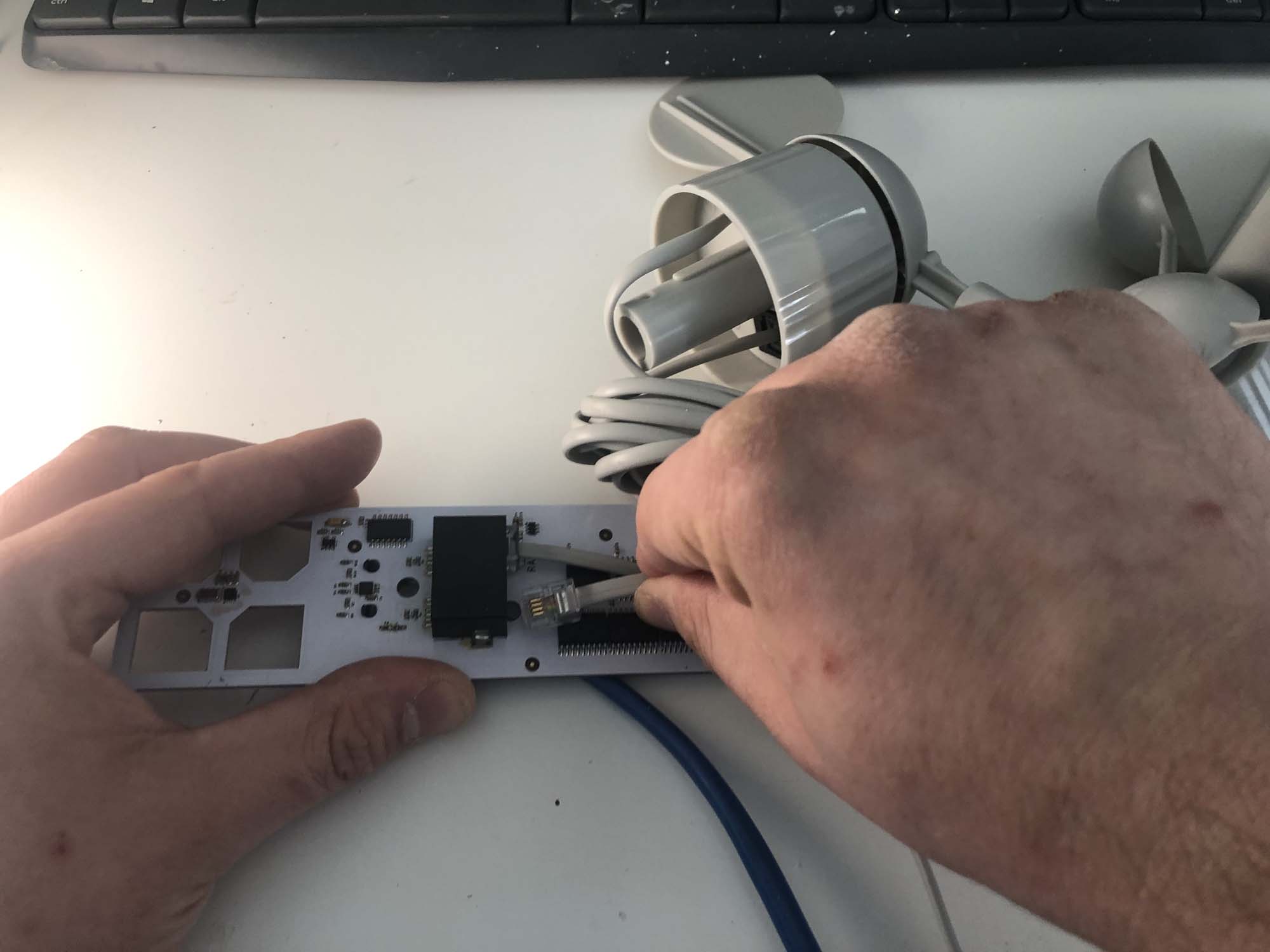
As the Ultrasonic Rangefinder may need to be some distance from the FieldKit station itself, the cables are long for the benefit of those who may need to place it further away. If the instruments are placed near one another, please use the included zip ties for cable management.
7. Explore Mounting Solutions
There are a few ways to approach mounting. Experiment and find a mounting solution that will work for your particular deployment location.
Zip-Ties to Mount and Secure
You’ll use the zip-ties to help mount and secure your Distance Sensor Enclosure. They are also useful to hold your hanging cable against whatever your Distance Sensor Enclosure is mounted to.
Other Options
You can also use a 1” hole in the cable plate on the FieldKit itself to mount the Ultrasonic Rangefinder with a ¾” NPS/NPT nut.
8. Congratulations! Now Test it Out!
You should now have an assembled Distance Sensor! Make sure you know how to place your Distance Sensor before heading out into the field. If you have questions, feel free to reach out to the FieldKit team.
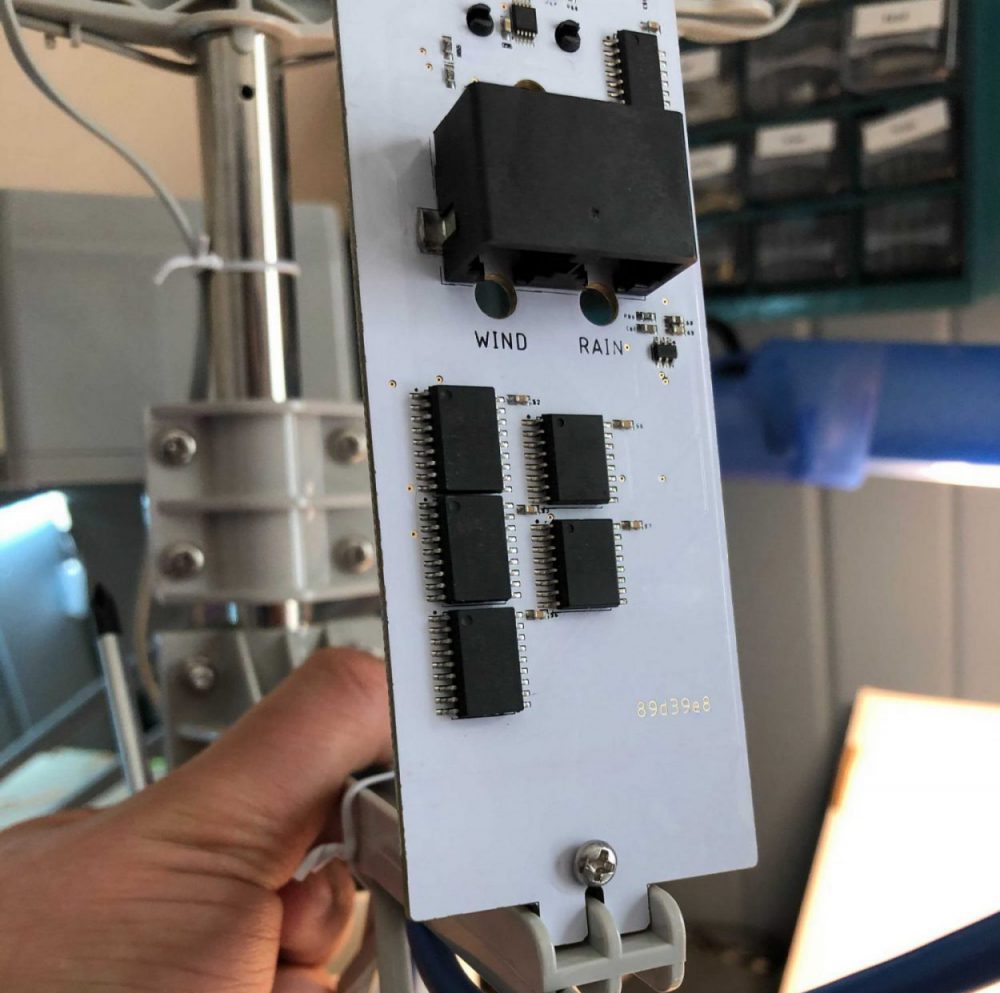
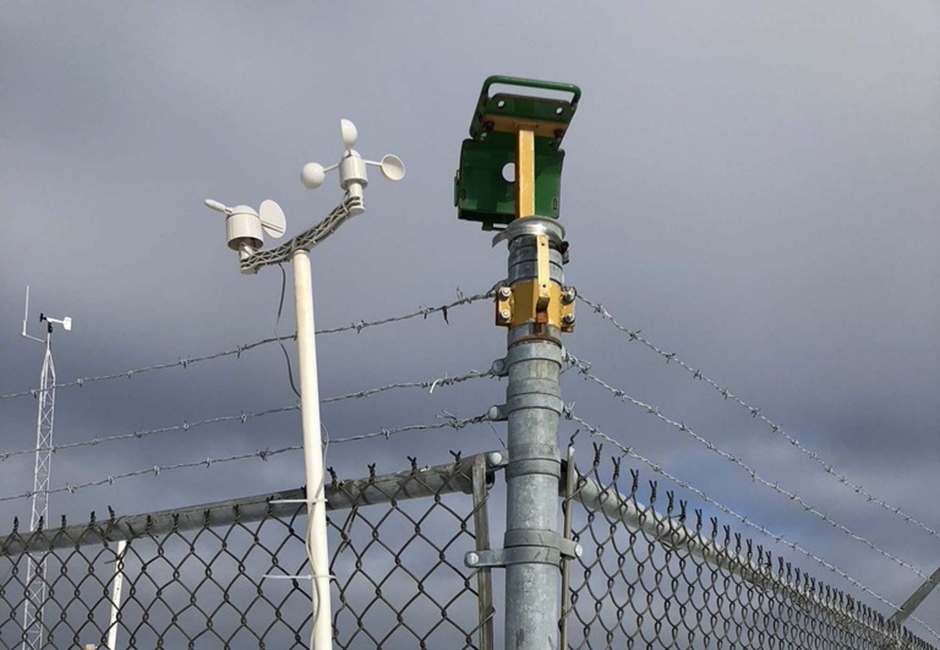
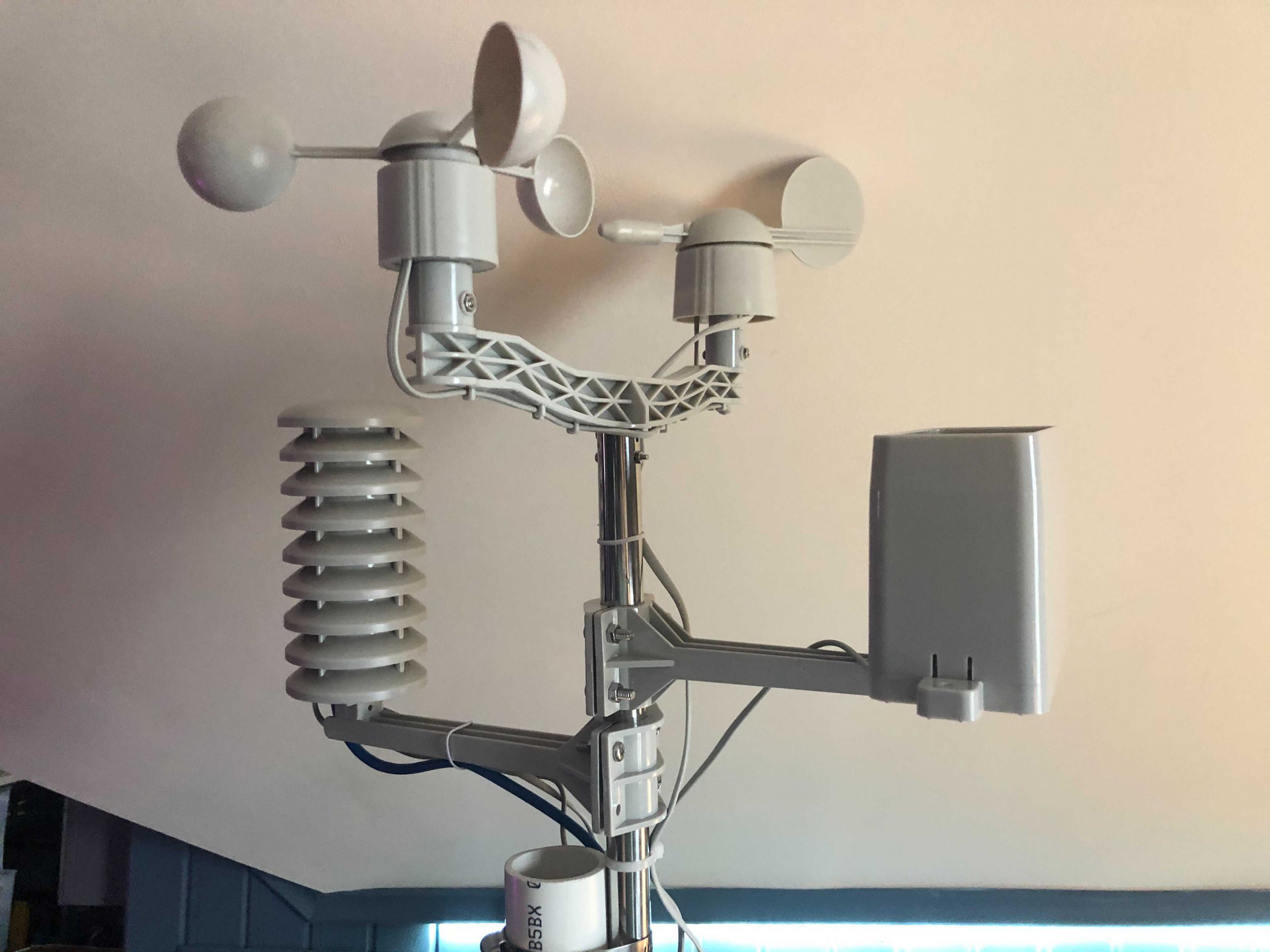
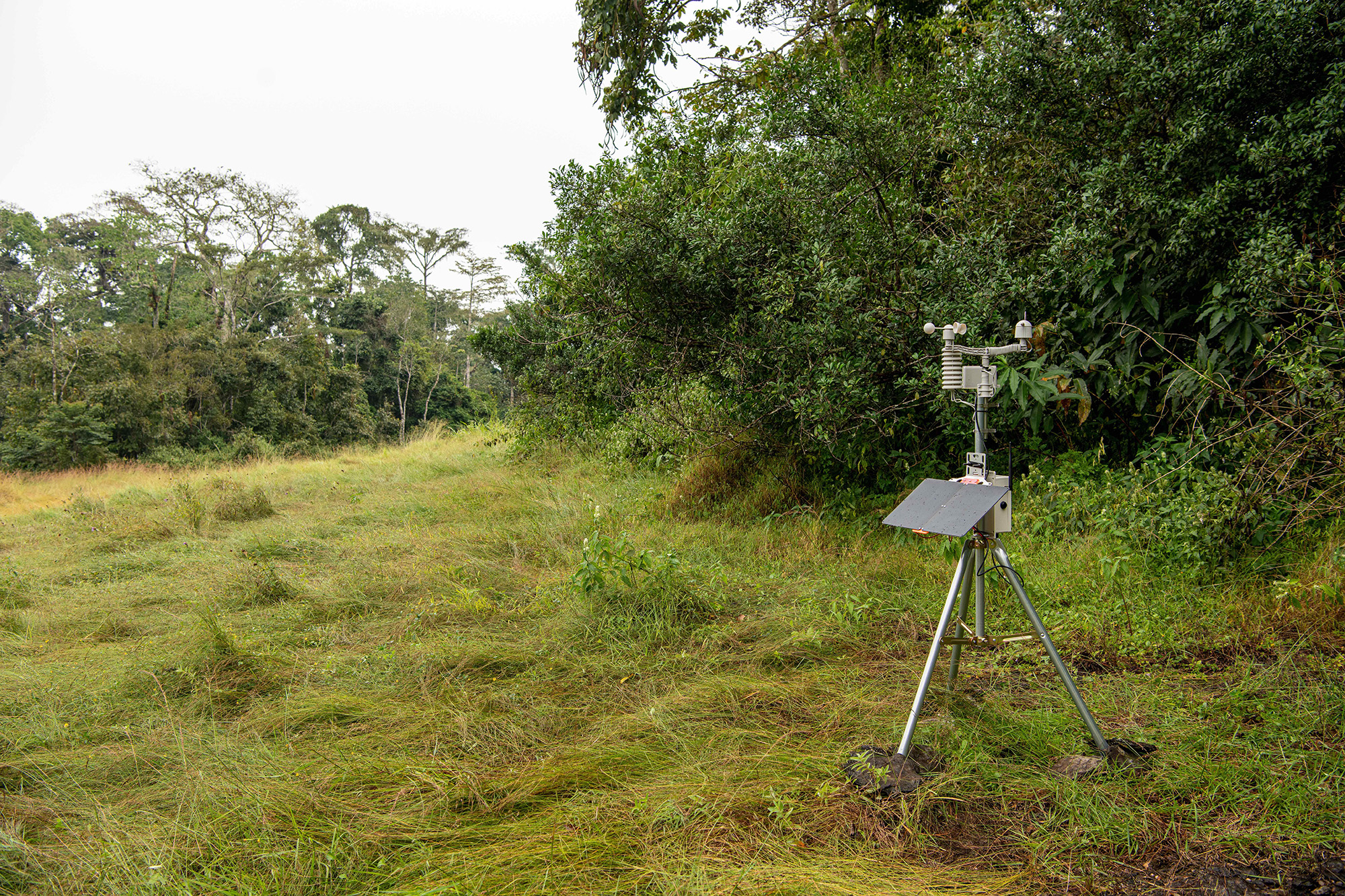
Weather Module Setup
Assemble Weather Pack
Your Weather Pack consists of a Weather Module Board, Weather Sensor Board, a CAT5 cable and a Weather Instrument Cluster (Rain Gauge, Anemometer and Wind Vane) plus accompanying cables and hardware.
1. Do you have everything?
Collect the following:
1) Weather Module Board
2) Weather Sensor Board
3) CAT5 Cable
4) Stevenson Screen + Arm
5) Rain Gauge + Arm
6) Anemometer, Wind Vane + Arm
7) Mounting Pole (2 parts)
8) Hose Clamp
9) Weather Instrument Cluster Screws
The Weather Module Board should already be attached to your station.
You will also need a compass—we recommend the Suunto A-10 Compass or equivalent—to align the wind vanes when setting up the Weather Instrument Cluster (not included).
As you unbox your weather instrument cluster, you will notice that the screws to construct each piece are packaged with the corresponding parts of the cluster. This is in addition to the screws that come with the rest of your FieldKit station.
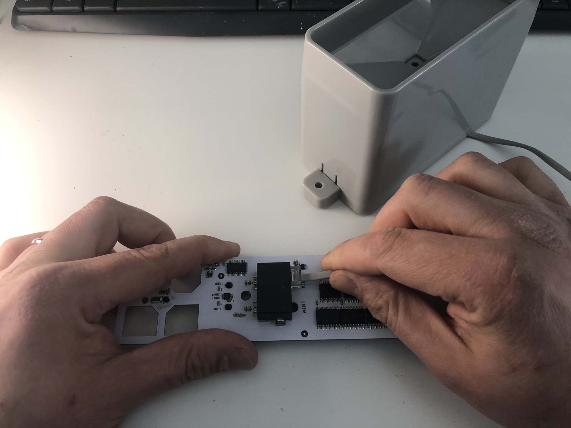
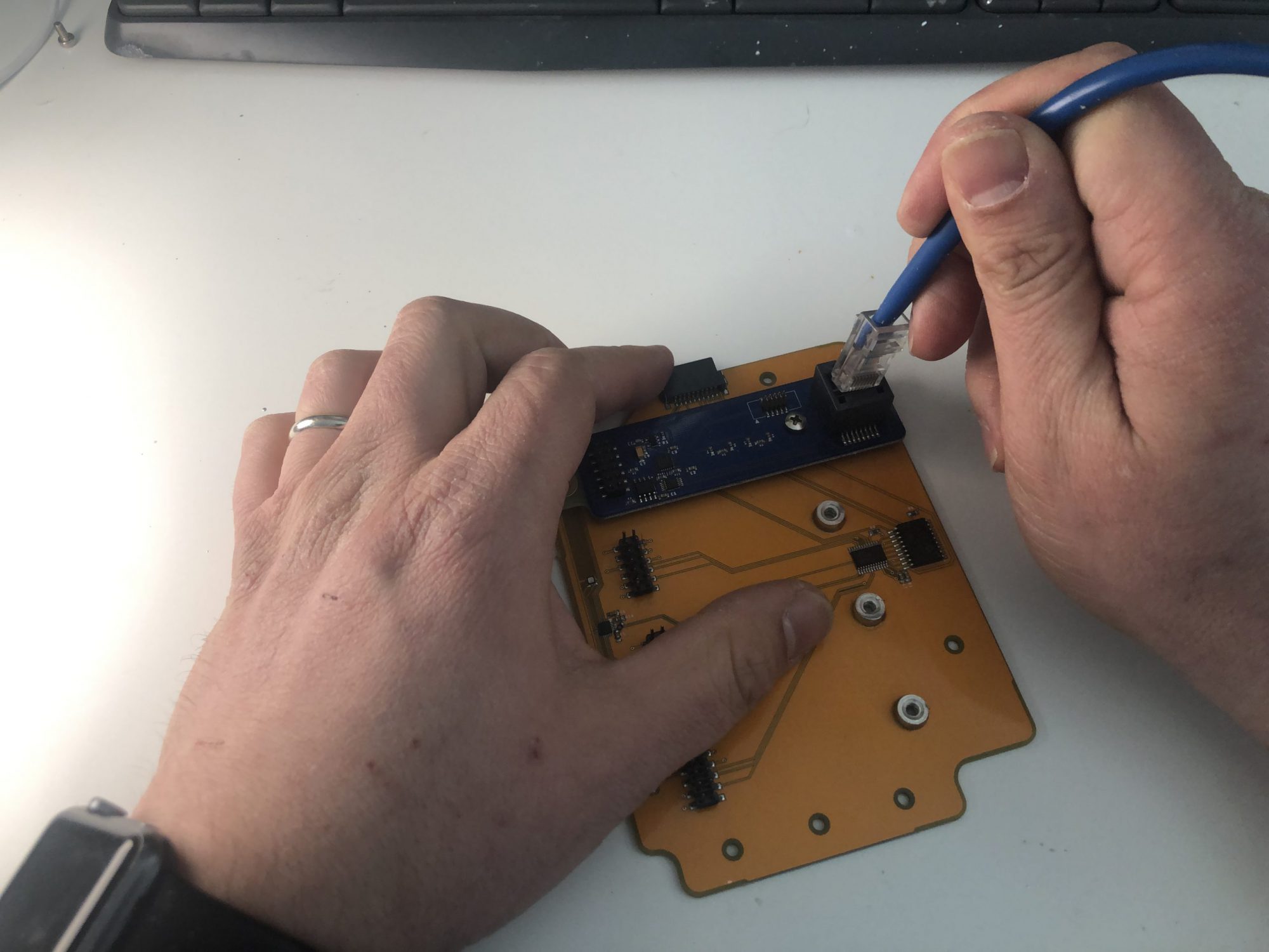
2. Insert CAT5 Cable into Weather Sensor Board
Insert one end of the CAT5 cable into the Weather Sensor Board.
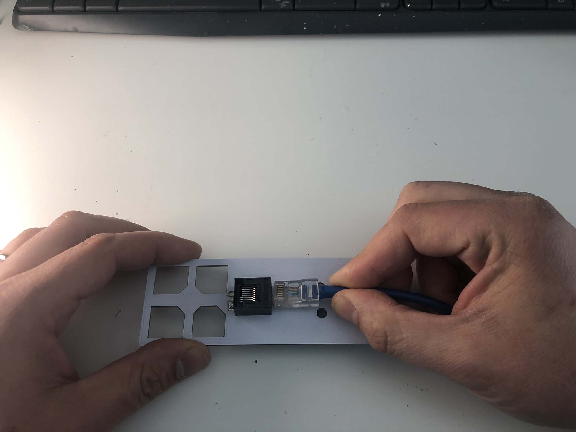
Insert Cable
Make sure you insert it in the right direction.
3. Connect Rain Gauge
The Rain Gauge measures rainfall. It doesn’t require emptying, as it’s a tipping-bucket type. Inside is a tipping bucket (a bit like a see-saw) with areas where rain collects. When one side is full, it tips over, emptying out the water. Push in the tabs on the sides of the housing and open it up to see how it works!
Insert Rain Gauge RJ11 Jack
Unravel the Rain Gauge wire. Note that that rain gauge wire has two wires exposed in the clear end of the connector (versus the wind gauge wire which has four exposed). Turn over the Weather Sensor Board, and insert the RJ11 jack from the Rain Gauge into the slot on the Weather Sensor Board marked “RAIN.”
Attach Rain Gauge Arm
Attach the Rain Gauge to the Arm with the screw provided.
4. Connect Wind Vane and Anemometer
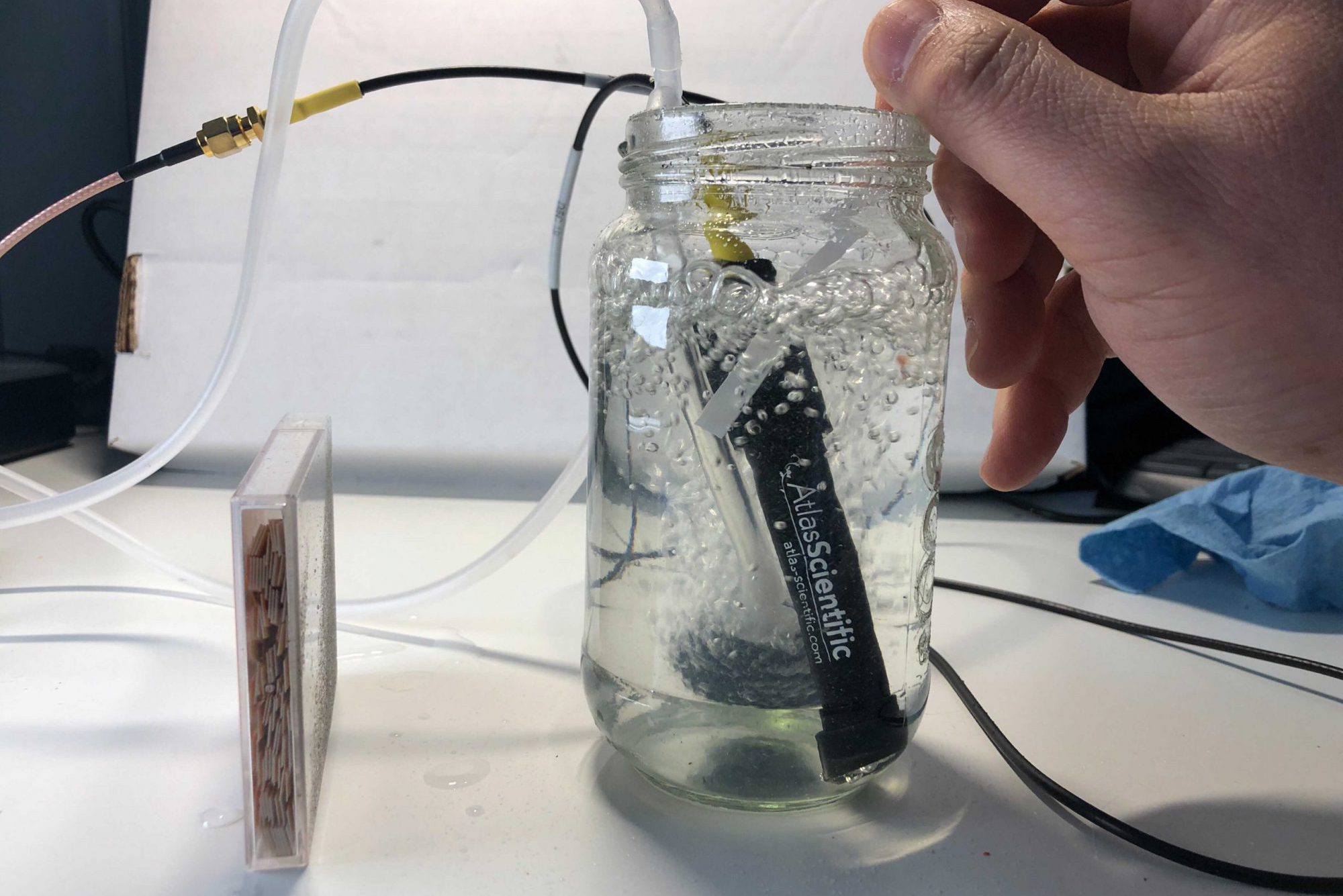
The Wind Vane shows you the direction that the wind is blowing, and the Anemometer measures wind speed.
Insert Wind Vane RJ11 Jack
Unravel the wires from the Wind Vane and Anemometer. Note that that wind vane wire has four wires exposed in the clear end of the connector and the anemometer wire has two wires exposed (same as the rain gauge wire which also has two exposed). Insert the RJ11 jack from the Wind Vane into the slot on the Weather Sensor Board marked “WIND.”
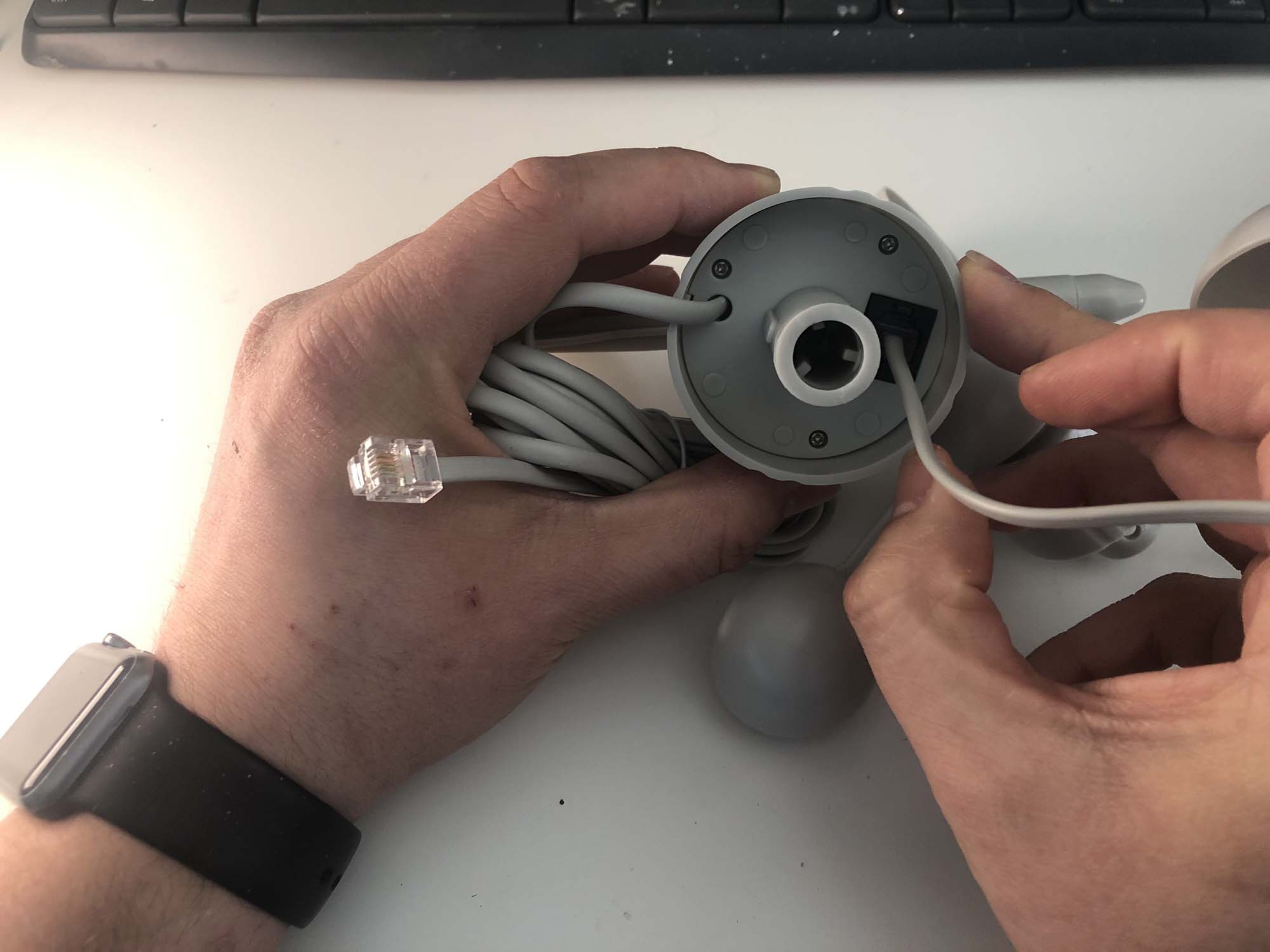
Insert Anemometer RJ11 Jack
Insert the RJ11 jack from the Anemometer into the Wind Vane so that they are connected (the Anemometer switch conductors are shared between the Anemometer and the Wind vane.)
Attach Anemometer and Wind Vane onto Arm
One by one, push the Anemometer and Wind Vane onto the arm, and screw them in.
5. Place Stevenson Screen
The Stevenson Screen is a breathable enclosure that protects the Weather Sensor Board circuitry from the elements without interfering with the sensors.
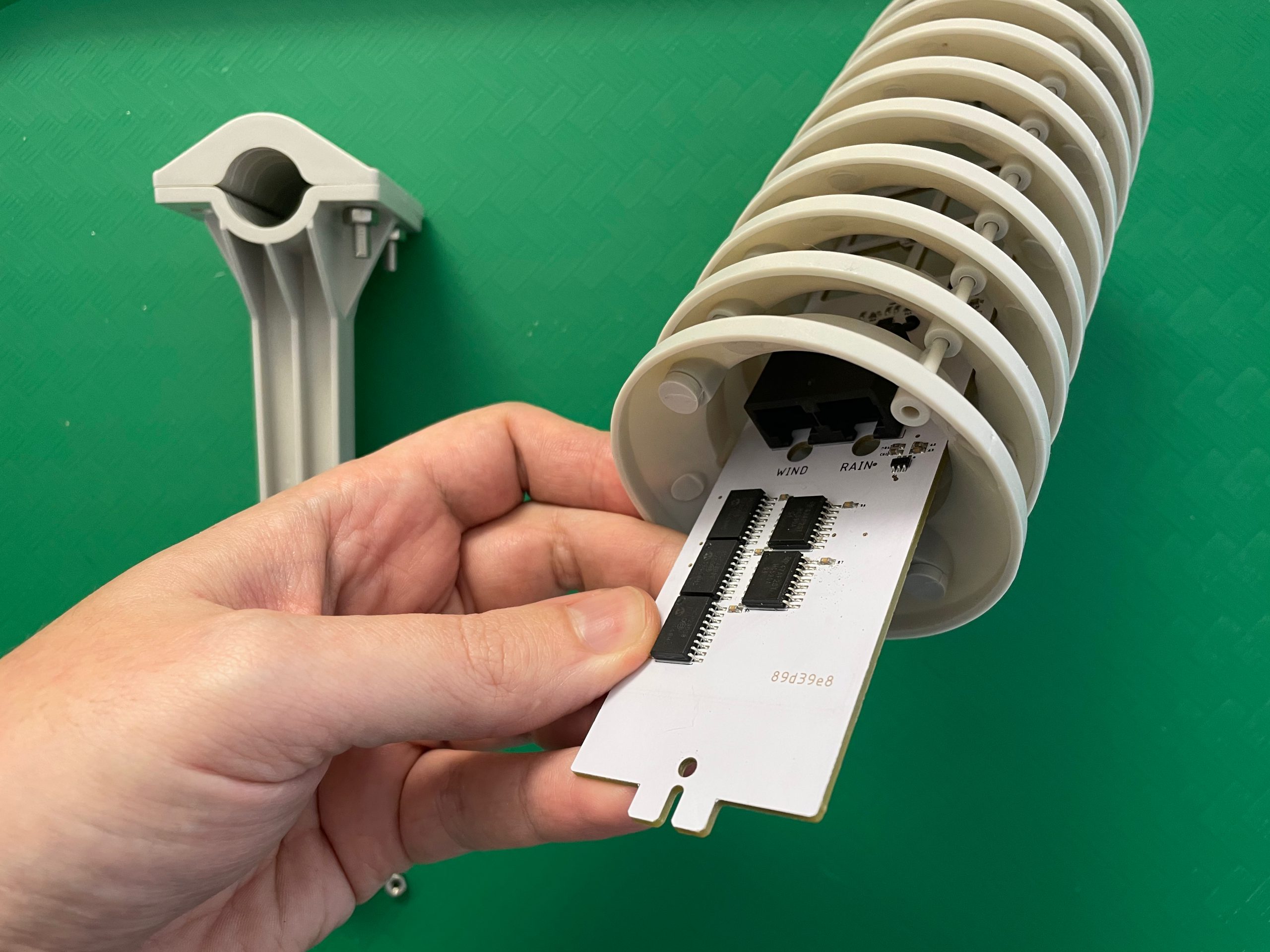
Insert Weather Sensor Board
Insert the Weather Sensor Board into the Stevenson Screen.
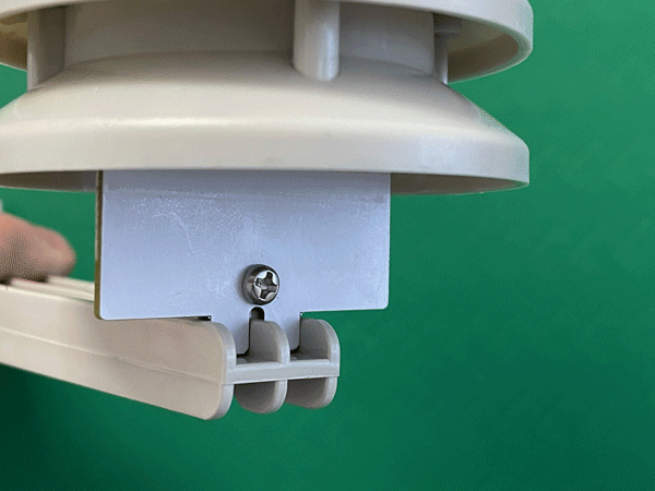
Attach Stevenson Screen Arm
Attach the enclosed board to the Arm with the screw and nut provided. To tighten, we recommend holding the nut with a pair of needle-nose pliers and tightening the screw by hand with your screwdriver.
6. Attach to Station
Time to plug into your FieldKit station.
Insert CAT5 Cable into Weather Module Board
Make sure that the other end of the CAT5 cable is securely inserted into the Weather Module Board.
7. Position Instruments
Now that everything is connected, assemble the pole and mount your instruments. It’s a good idea to do all this before you head out into the field to gather any extra hardware needed, and land on an optimum configuration.
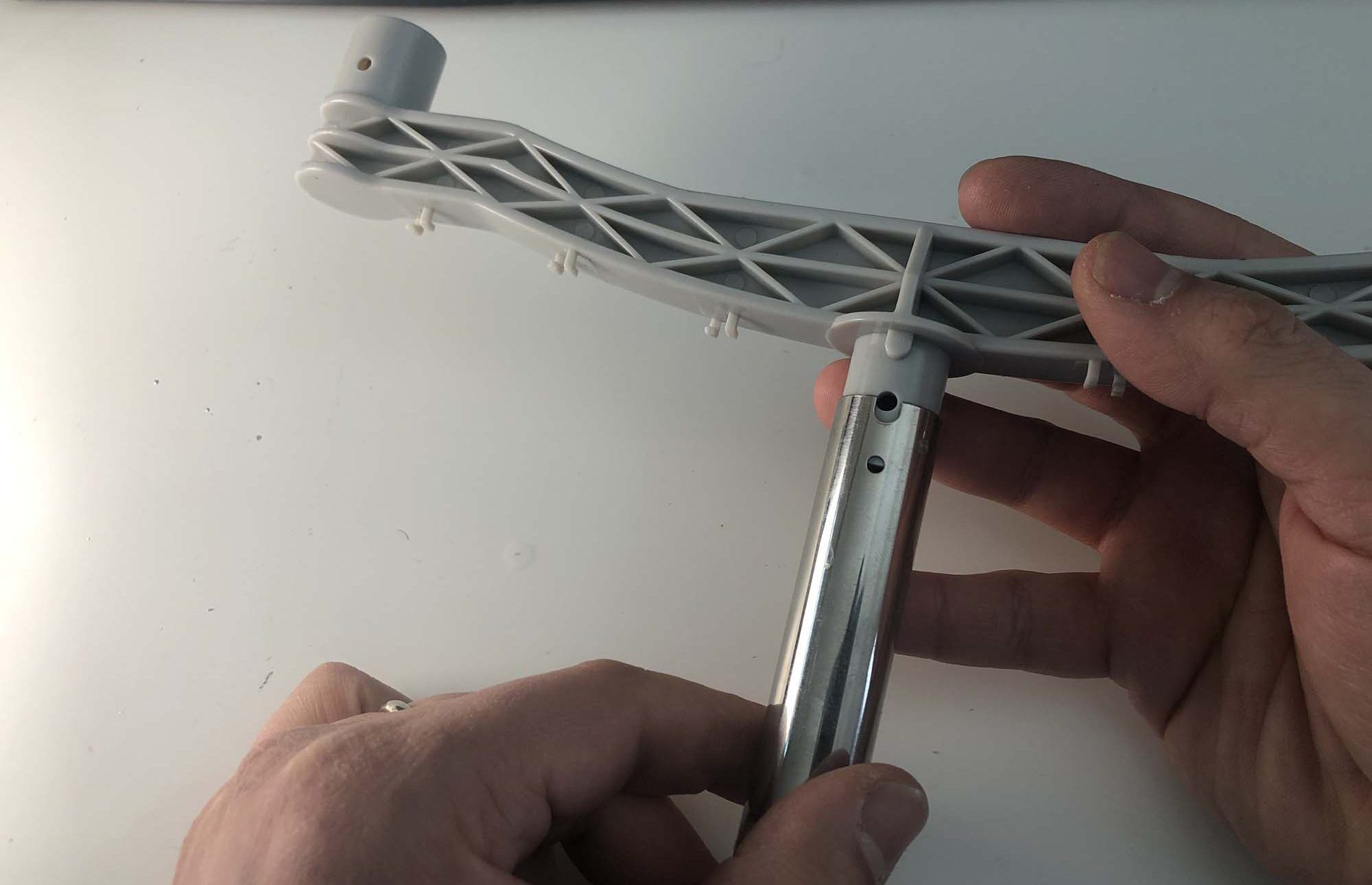
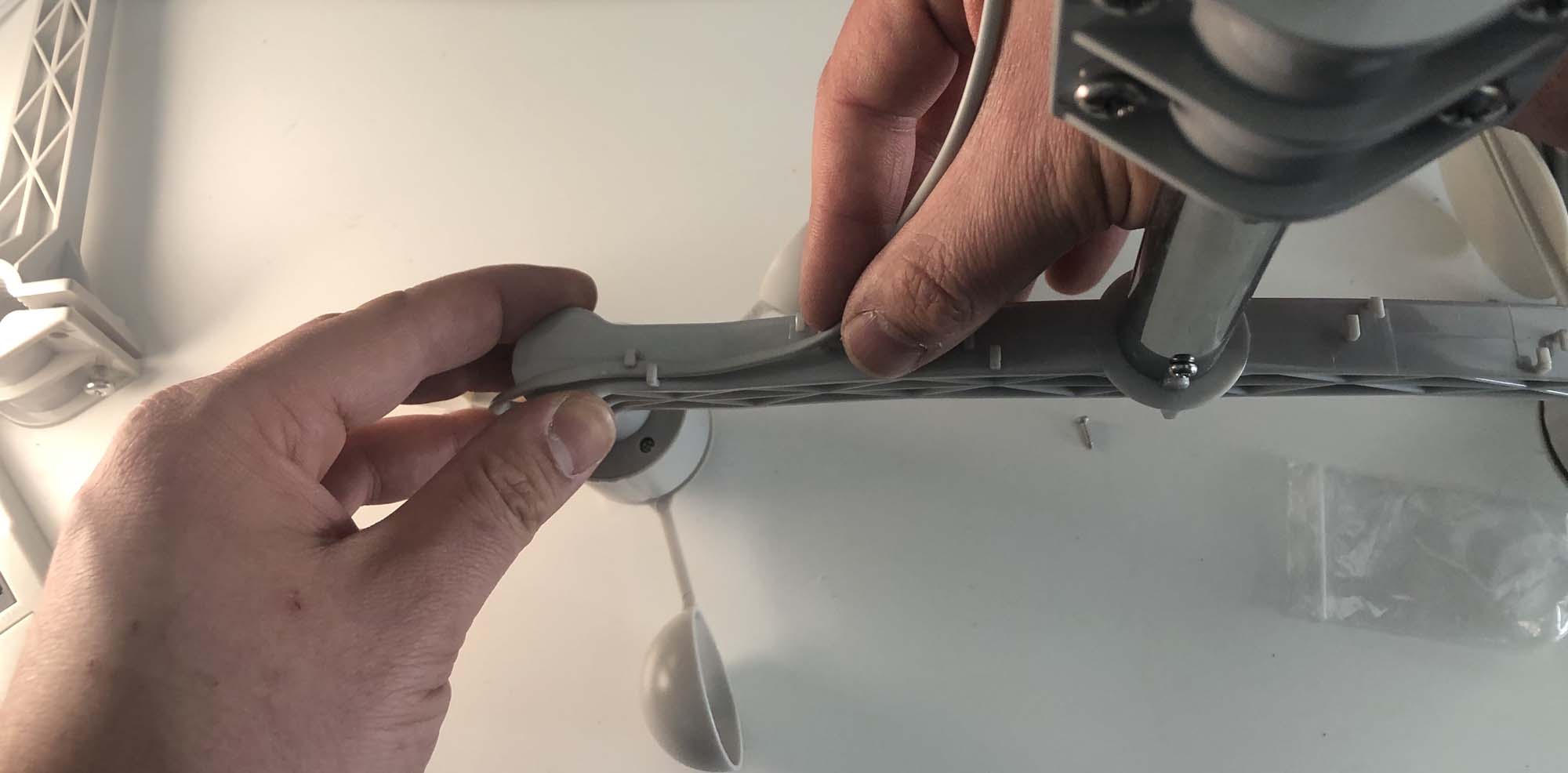
Assemble Mounting Pole
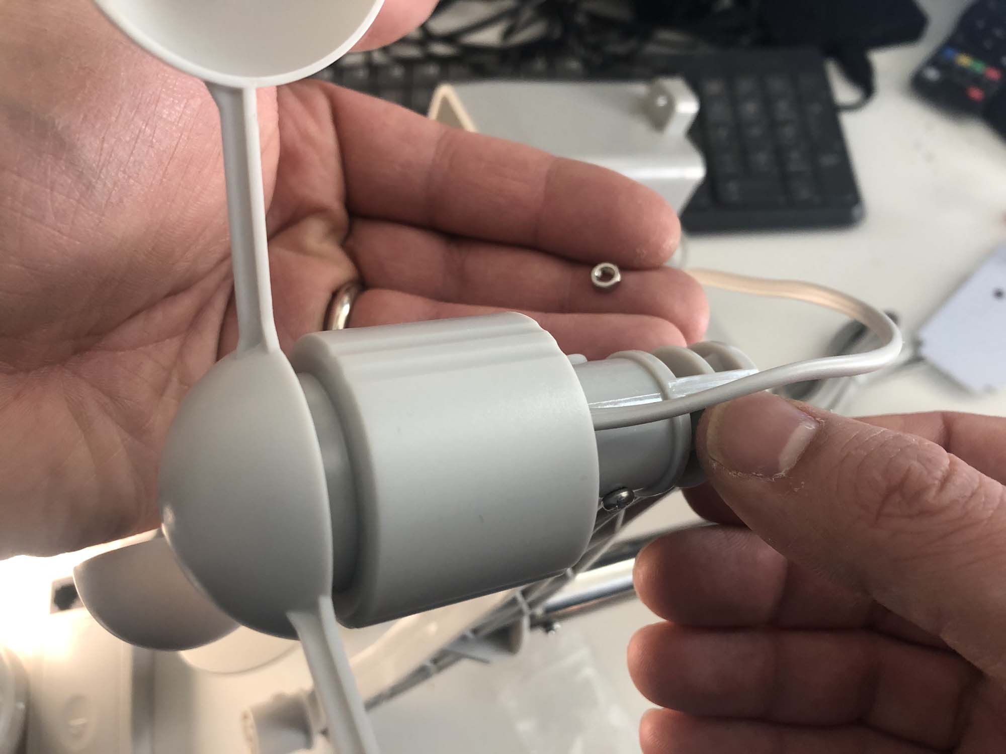
The mounting pole comes in two pieces. Take a moment to identify which piece has a notch at the end, then slide the two pieces together to create one longer pole. The notched end should be at the top of the assembled mounting pole when completed.
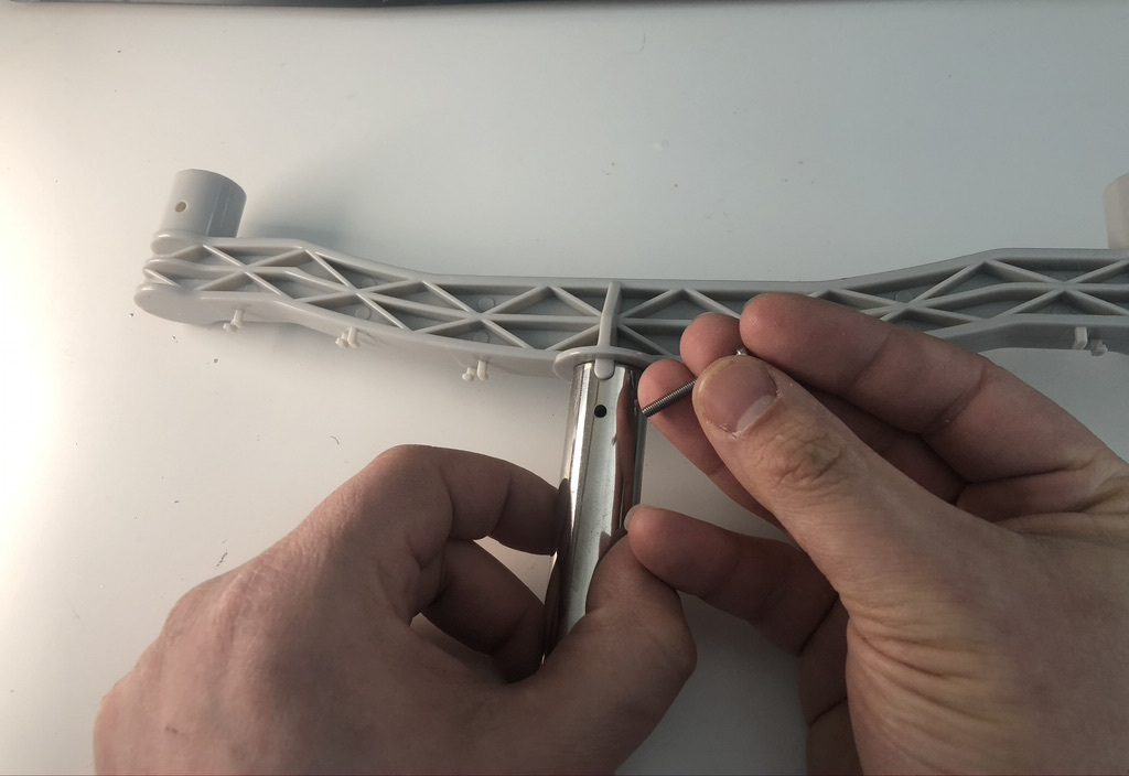
Add Anemometer and Wind Vane Arm to Pole
Add the Anemometer and Wind Vane Arm to the top of the assembled pole and snugly line up the notch at the end of the mounting pole with the corresponding area on the arm and note the screw holes in each. Use the included screw to secure the arm to the mounting pole.
Add Stevenson Screen and Rain Gauge Arms
Take the Stevenson Screen Arm and Rain Gauge Arm, and loosen the pole openings by unscrewing the screws slightly.
Slide the one assembled pole through the instrument arms, and tighten the screws so that they are secure on the pole.
8. Cable Management
As the Anemometer and Wind Vane need to be at least 5 m above open ground to give you representative wind data, the cables are long for the benefit of those who choose not to place the Stevenson Screen close by. If the instruments are placed near one another, please use the included zip ties for cable management.
Slide Wire into Clips
On the bottom side of the Anemometer and Wind Vane Arm there are clips to hold the wires in place. Slide the wire from each instrument into the clips.
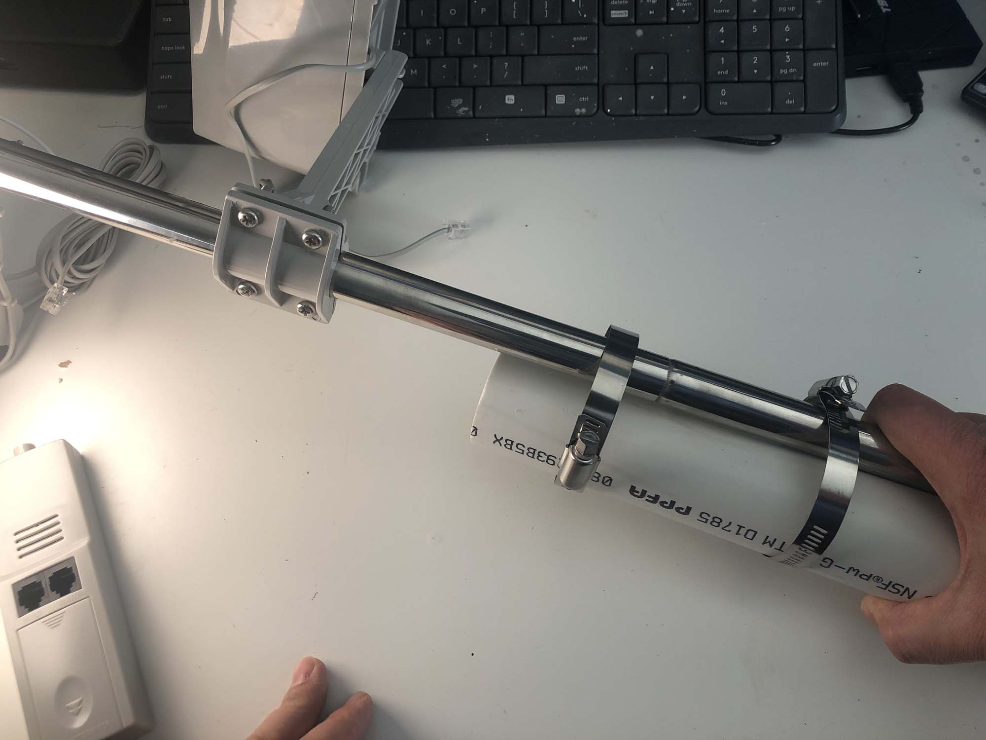
Secure onto the Mounting Pole
Run all of the remaining wires down the assembled pole, and secure them with the hose clamps (you may also want to source some zip ties to be extra secure). This will avoid them being yanked out of the circuit boards by strong winds.
9. Explore Mounting Solutions
There are a few ways to approach mounting. Experiment and find a mounting solution that will work for your particular deployment location.
Hose Clamps to Mount and Secure
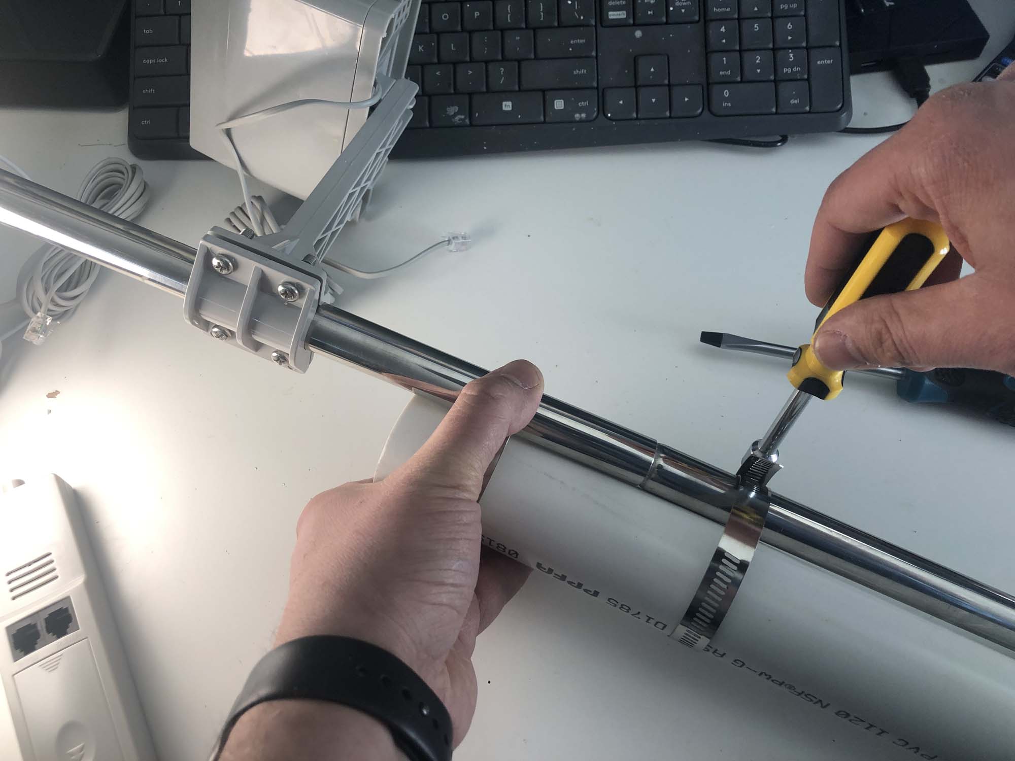
You’ll use the Hose Clamps to help mount and secure your weather cluster. They are useful to hold your hanging cables against the pole and attach the pole itself to a mast in the environment that reaches the appropriate height to take accurate measurements (more than 5 m above the ground.) Tighten the hose clamps using a flat head screwdriver.
Other Options
Plan for the terrain of your deployment location, and identify which type of mast in the environment you will use to mount your Weather Instrument Cluster. The mast you have in mind might be thicker than the diameter of the Hose Clamps provided, so visit your local hardware store for something with the right specifications.
10. Congratulations! Now Test it Out!
You should now have an assembled Weather Instrument Cluster! Make sure you know how to place your Weather Cluster before heading out into the field. Check out the Weather Deployments section and do a test run at home to make sure you’re prepared.
Calibrate Weather Sensors
The sensors belonging to the Weather module are factory calibrated and do not require additional field calibration.
Congratulations!
Your readings should now be accurate.
Remember, these are only live data readings at this stage. You still need to complete the deployment process and hit “Record Data.”
Set Up Solar (Optional)
You may have purchased a FieldKit Solar Panel. If so, we recommend assembling and testing the panel (by attaching the cable) at least once before leaving home, so that you know everything is in working order and you have a plan for deployment. If you prefer to transport the cable separately from the panel, you can simply disassemble them before heading out to the field and re-assemble onsite.
High-pitched whining or beeping noises may sometimes be audible, especially when charging from solar power; these are expected and part of normal operation.
Assemble Solar Panel
To assemble your solar panel:
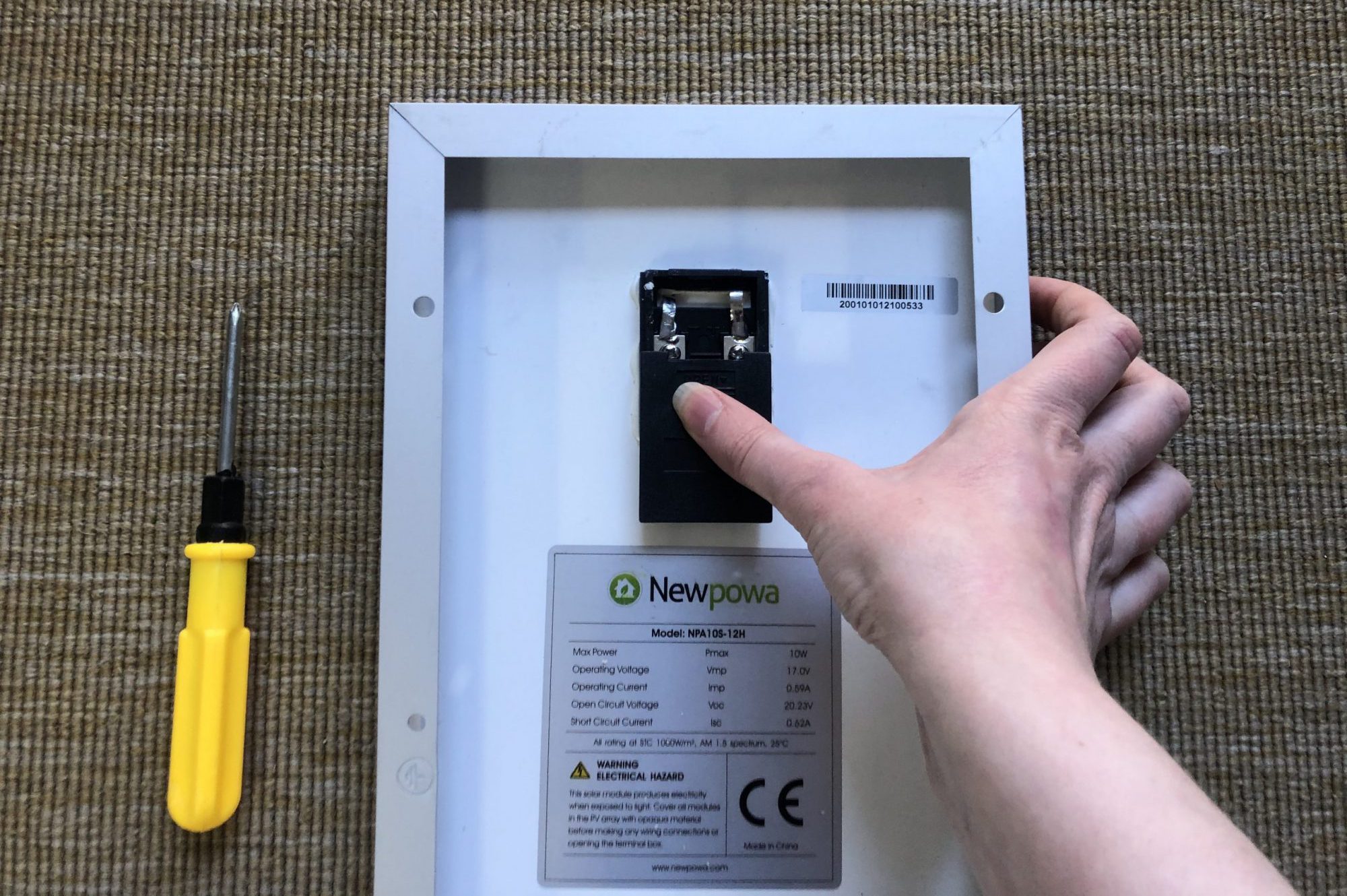
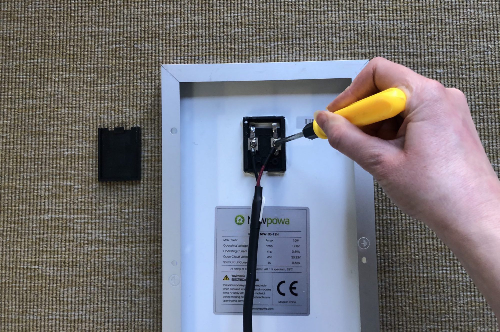
1. Slide Off Box Lid
Turn the panel onto its front, so the back side is facing up. You’ll see a black box on the back of the panel. Slide off the box lid by applying some pressure where it says “OPEN” and pulling down.
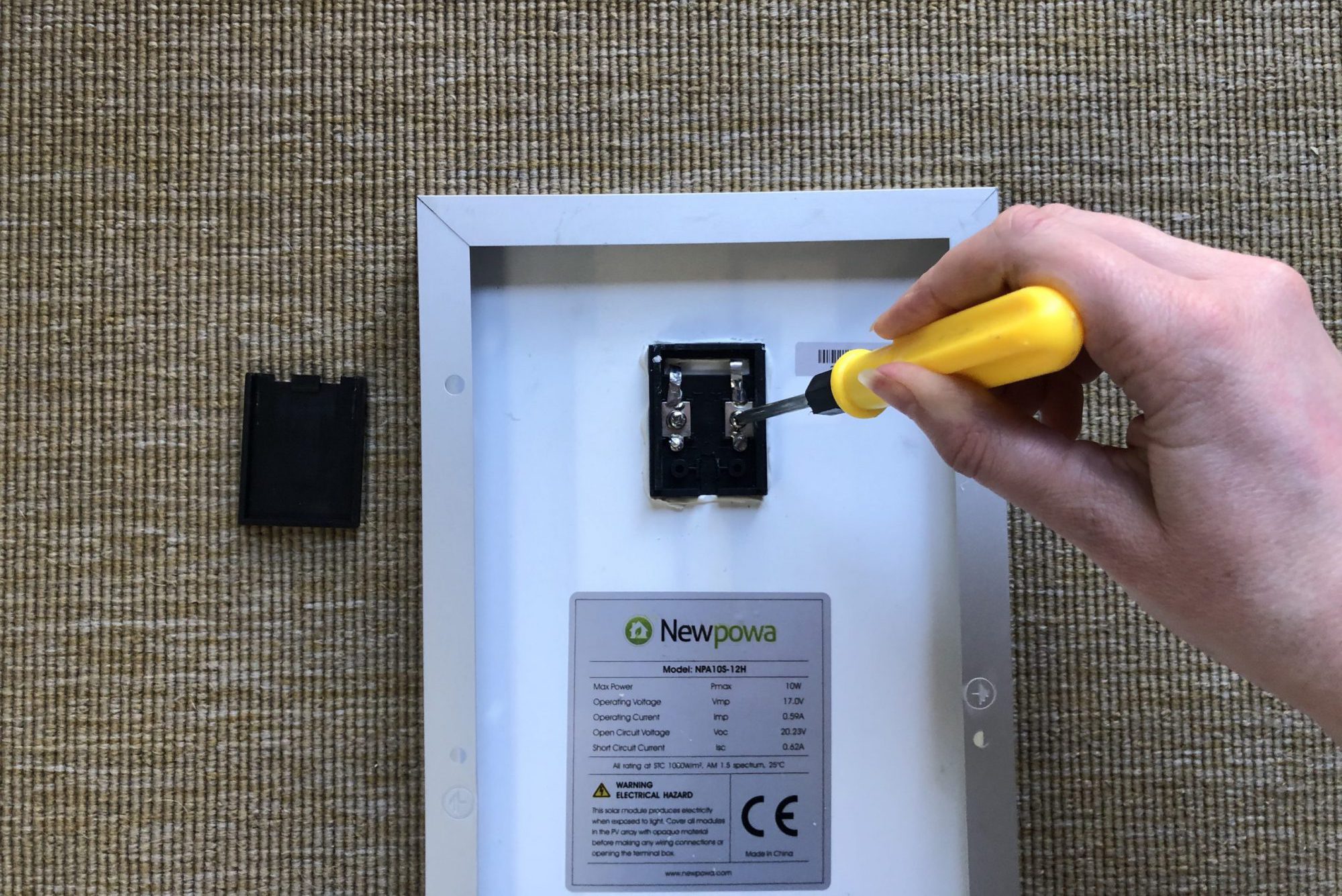
2. Remove Screws
Remove each of the two screws and washers from the threads within the box.
3. Find Cable
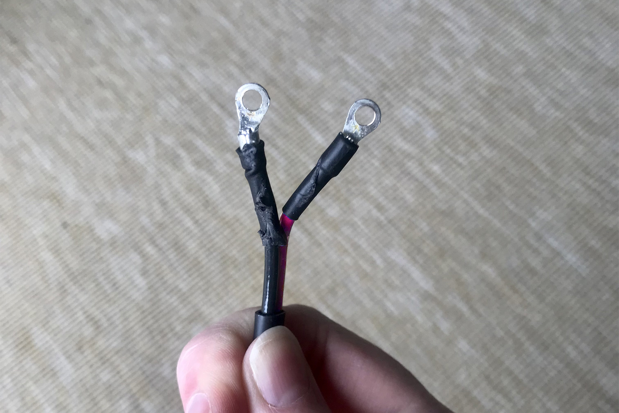
Locate your solar panel cable. Take the end that terminates in two wires, one red and one black, each attached to a metal lug (a circular metal finding).
4. Attach Cable
Place the two lugs over the threads in the box, then reinstate the screws and washers. Screw them back into place.
Be sure to assign the lug on the red cable to positive ( + ) and the lug on the black cable to negative ( – ).
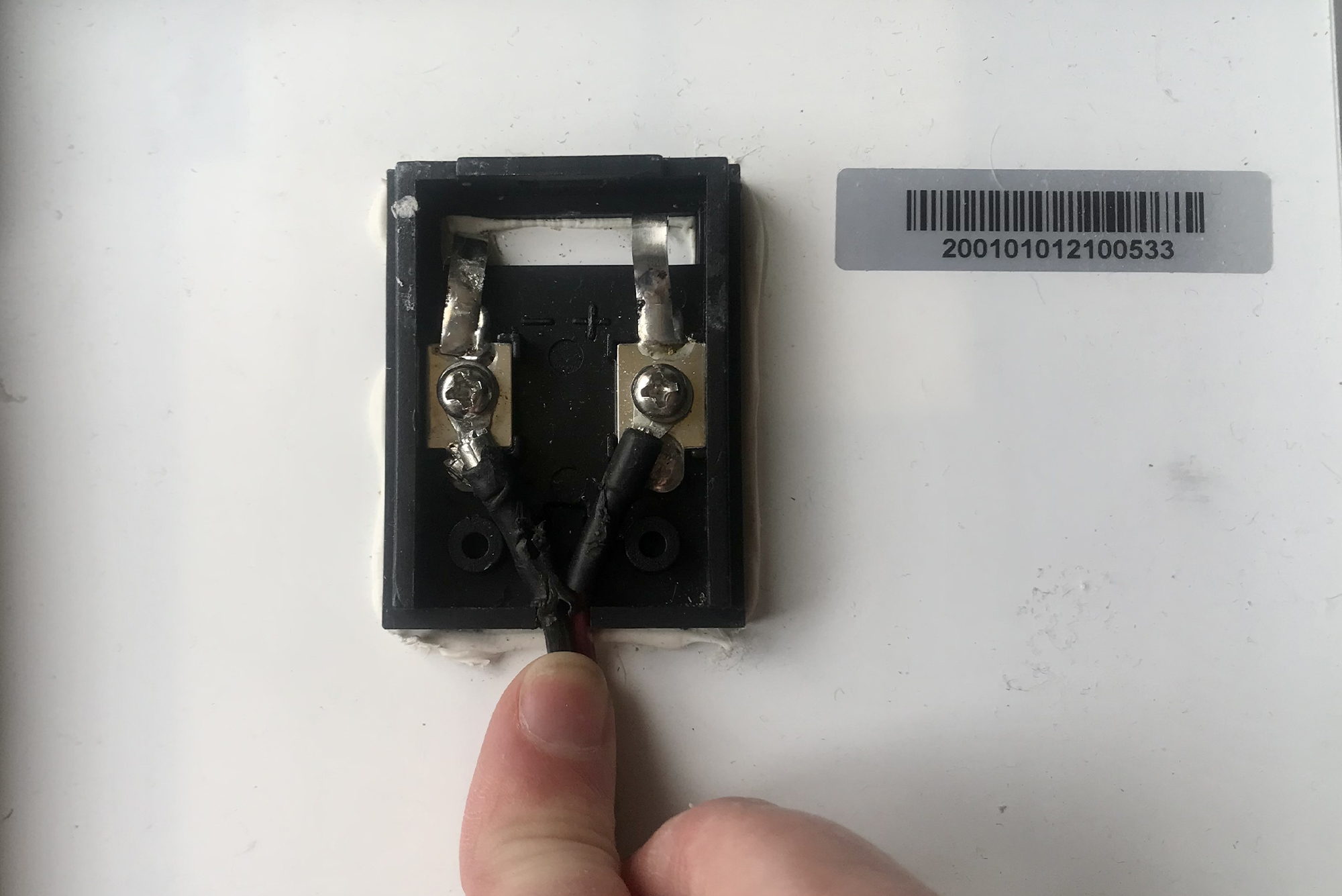
5. Sculpt Wires
Bend and mold the wires so that they fit into the groove. They are quite stiff, so don’t be afraid to push them with some force. It will be a snug fit.
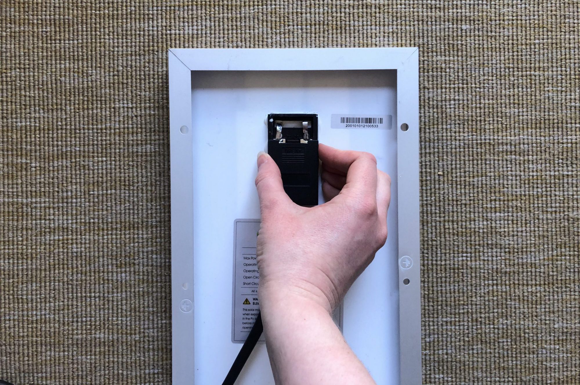
6. Slide On Box Lid
First, make sure everything is sitting as flat as possible. Then, apply some pressure and slide the lid back onto the box.
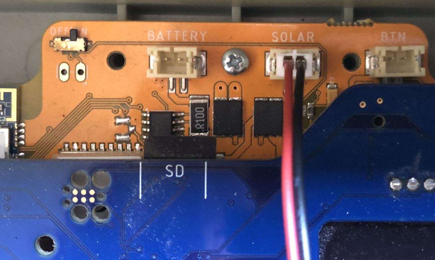
7. Insert Solar Cable
Take the other end of the solar cable and insert it into the top middle socket of the Upper Board where it says “SOLAR.” When inserted, the cable should have the red wire on the left and the black wire on the right–if this is not the case with your cable, please reach out to FieldKit so that we may replace your cable.
Before inserting the battery, solar and button cables, double check that you are connecting them to the correct sockets (labeled “BATTERY,” “SOLAR” and “BTN”). Inserting cables into the wrong sockets can permanently damage your FieldKit.
Place Solar Panel
During deployment, you’ll need to ensure you’re placing your solar panel in the optimum conditions to charge the battery that’s powering your station. Read more about this in our section on Solar Deployments and in our Care Instructions section.
Ready to Deploy
Now that you know your live data readings are accurate, you’re almost ready to deploy your station.
Before heading out into the field, take the time to plan your deployment. How often and at what time of day will you take readings? Consider where you’re going. Think through the land regulations, safety considerations, tools needed for the job, replacement parts and the weather conditions. We encourage questions and discussions about these topics and other tips for optimum deployment in the FieldKit Community Forum.
We believe that documentation is important. So while early versions of FieldKit will automatically start recording data, we’re working on new functionality to encourage users to realize the benefits of deploying in order to start recording data. That’s how this Product Guide is written.
Pre-Deployment Checklist
1. Data Capture Plan
Consider the appropriate data capture schedule for your project. How often and at what time of day will you take readings? Where will you deploy your station?

2. Take Notes and Pictures!
Plan to help your team and the community better understand their environment and improve future troubleshooting with some contextual notes and pictures. You’ll use the app to do this in the field once you initiate the deployment process.
3. Access Issues
Check in with landowners and stakeholders before deploying your FieldKit. If deploying on state- or federally-owned land, review protocols or contact park personnel. Obtain permits as needed.
4. Double-check Station
Ensure your FieldKit Station is fully constructed and operational before taking it into the field. Assemble your cable plate if you haven’t done so already. If you are shipping your FieldKit or otherwise expect a long journey, we recommend transporting your station with the cable plate and probes removed and safely packaged and then re-assembling your cable plate when you reach your destination.
Check out our Care Instructions to ensure you’re setting yourself up for success. Do not skip this step.
5. Data Storage Back-up and Firmware Updates
We recommend that you check for firmware updates and update your station firmware when you are near your station and have a reliable internet connection. Do this before you go into the field to deploy your station or plan to leave it alone for a long period of time. For detailed instructions on how to update your firmware, check out Update the Firmware.
In order to back up your data and update your firmware, (which we highly recommend), make sure a microSD card* is in the FieldKit cardholder on the Upper Board.
6. Verify Power Source
What are your power sources? If you’re not using a solar panel or plugging into power directly, is your FieldKit fully charged or equipped with fresh batteries?
7. Consider Mounting Materials
Are you mounting your FieldKit to a post? To a tree? If leaving it in the field for an extended period, make sure you’ve got the materials to attach it safely and securely without damaging the environment.
8. Leave (Almost) No Trace
Beyond your FieldKit Station, be sure to clean up after yourself and leave the location as you found it, so take a trash bag. In the future, when you’ve completed your deployment and removed your FieldKit, it should be like you were never there!
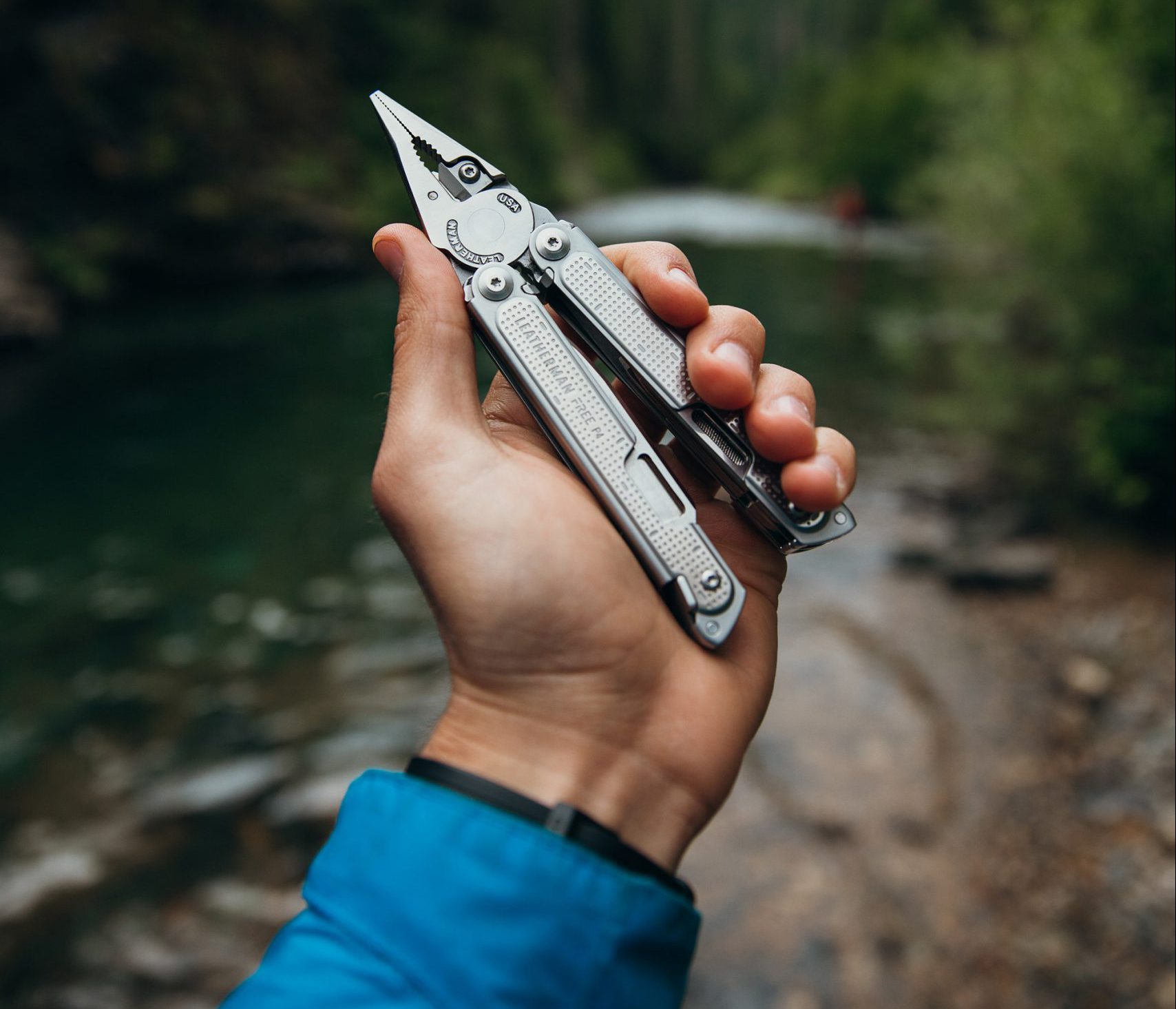
9. Weather Forecasting and Extra Tools
Check the weather forecast and prepare accordingly. Bring a multitool with a screwdriver for last-minute adjustments in the field.
10. Take Care of Yourself!
Tell someone where you’re going, especially if it’s going to be remote. Respect nature—beware of rough terrain or dangerous animals. Read more on Safety in the Field here.
Unsure About Anything?
If you have any questions or concerns about deployment, the FieldKit Community Forum is a great place to go for help. Unsure how to set up your station in a new environment? Curious about how to plan for bad weather? Here you can learn from other people using FieldKit stations (as well as the FieldKit team).