Module Mayhem
So back in “Origin of Species” I talked about the big-picture hardware architecture of Darwin. Let’s talk a little bit more about the architecture of modules, and why we made them the way we did.
So what don’t we want in FieldKit Modules?
We don’t want to have to manually configure each module.
Please, no jumpers, dip switches, or solder blobs to give them each a special address so as not to collide with another one.
We don’t want to have to tell Fieldkit everything.
Like that a module has been inserted, or in what slot, or what kind of module it is.
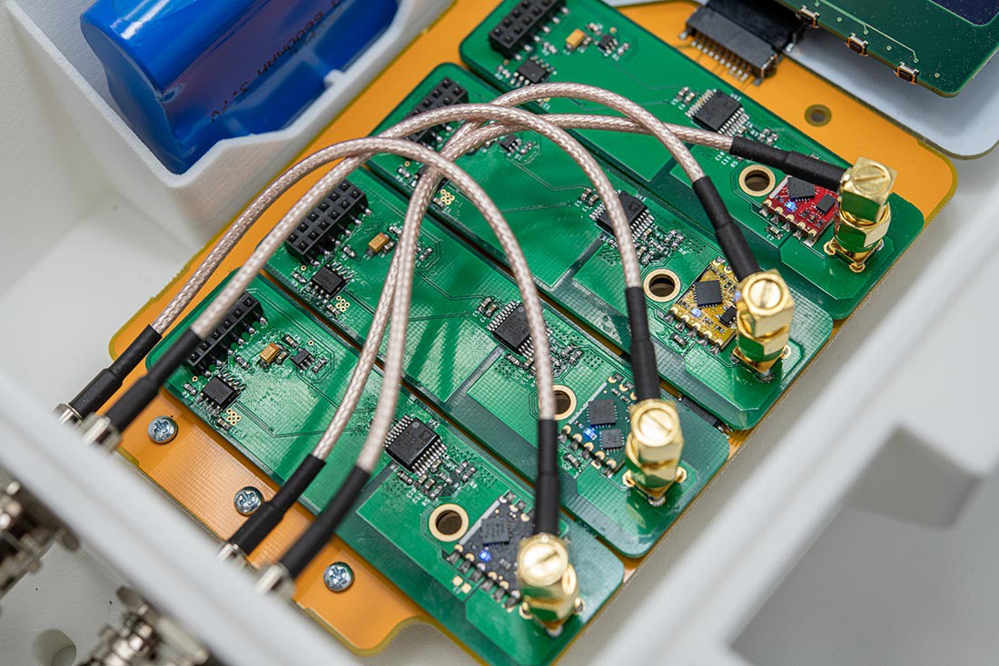
We don’t (typically) want to connect modules with cables.
They’re bulky, fiddly in tight spaces, and don’t provide physical support for the systems’ hard-knock life.
We don’t want the module to be powered all the time.
Batteries and Solar Panels are the most common way of powering FieldKit stations out in the world, so power consumption is always a concern. A module should come online at the selected interval, take a measurement, and shut off. We can’t rely on every future IC or sensor having effective power management on-board.
This is a perfectly lovely set of aspirations, but several of them seem to be incompatible with using i2C, which is ubiquitous. Enter Our Hero : Texas Instruments’ TCA9548 – an i2C Multiplexer. This solves a lot of problems:
Address Collisions.
If each module is an address-space to itself, multiple identical modules can be connected and not collide. Cute, right?
Module Identification.
Since i2C address collision is no longer a thing, each one can have an EEPROM on a known address which contains information about itself, so Fieldkit can identify them in a slick and automatic way. Modules needing calibration can also carry calibration data on that EEPROM, which is nice if somebody, say, moves it from one slot to another, or from one station to another.
Module Detection.
Each ‘client’ side of the i2C multiplexer requires pullup resistors, like any other bus. If you put the pullups on the module, only slots with modules plugged into them will have a high SCL line with the bus at rest, which makes detecting the presence of modules easy.
So what does our final bus look like?
Power
Modules are expected to do their own regulation and obey their Enable pins, so unregulated power and ground are provided. A regulated 3.3V line is also provided for the odd cases where some piece has to stay running even when the rest of the module is asleep. And Enable line is provided to turn the module on and off as required.
EEPROM Protection
A few modules require an onboard microcontroller. In these instances, the easiest way to pass data between modules and FieldKit is to stash it in the EEPROM we also use for module identification. This requires a negotiation line so you can prevent them from trampling all over each other.
i2C Bus
Necessary and ubiquitous.
SPI Bus
This is mostly provided as a safety measure. We don’t presently have any modules which require it, but it doesn’t pay to assume we never will.
Mechanical Considerations
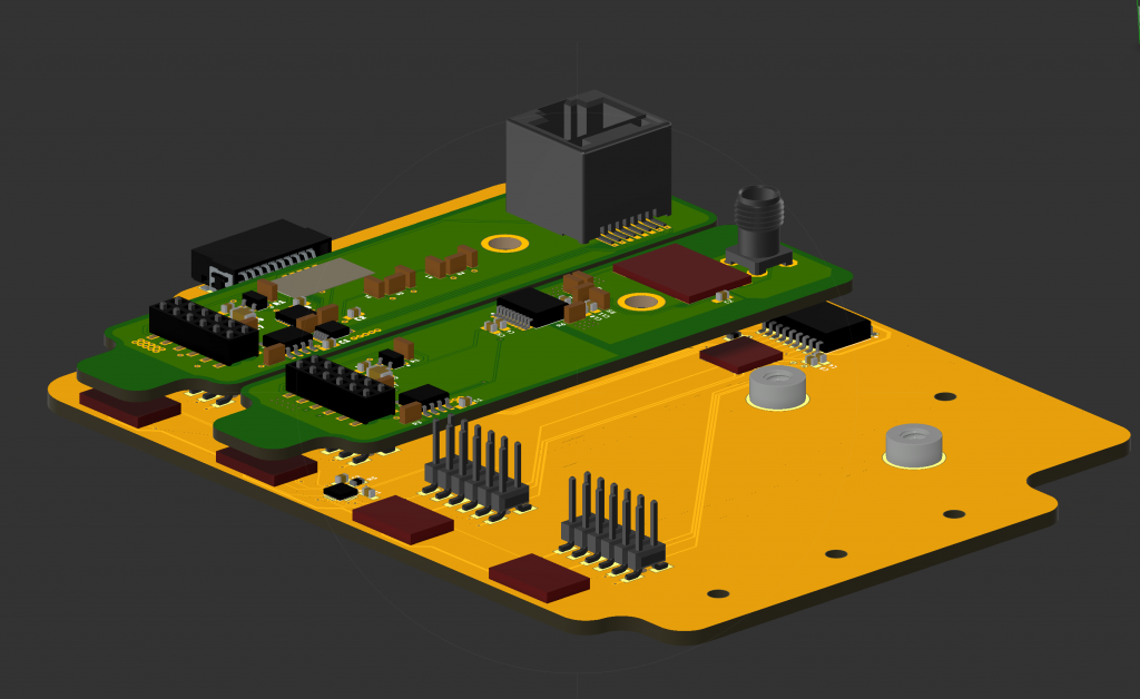
Modules have cables connected to them which might be heavy, and we don’t want the leverage tearing headers off the boards, so while we use bog-standard 12-pin male box headers on the FieldKit side for their ubiquity and strength, we use a somewhat less common female header where the pins pass through the PCB via holes underneath the connector. This lowers the center of gravity and available leverage on the pins significantly.
For belt-and-suspenders levels of resilience, we also have threaded standoffs on the backplane, with matching holes in the modules so they can be firmly secured in place. This seems excessive until the first time you drop one from a ladder.