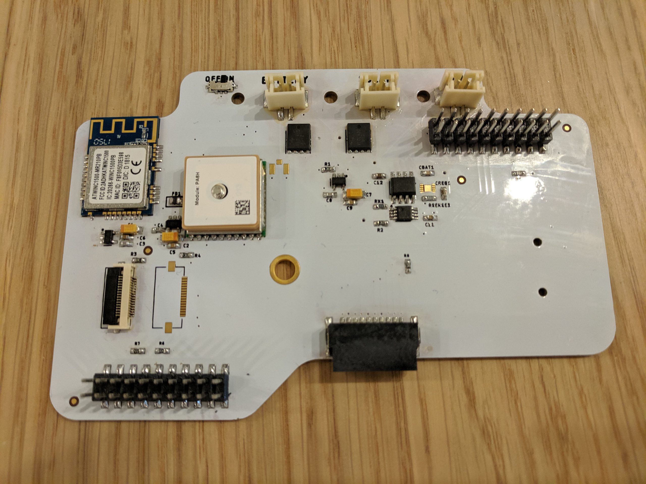
Designing Lower

There are not a lot of surprises here, but the power system is surprisingly hard to simplify. It seems simple enough, Battery, Solar Panel, USB power, but edge cases pile up quickly! In any event, there’s a battery charging IC (MCP7384) and a Maxim ‘fuel gauge’ style monitor (MAX17055) and their support circuitry.
The Wi-Fi and GPS duties are handled by a pair of Venerable modules (ATWINC1500 and FGPMMOPA6H). “Venerable” here is a word I use instead of “A bit long in the tooth.” and they’re the things most likely to be replaced in the near future. Each of them has a dedicated voltage regulator, and there’s a third for all the stuff up on the Upper board. Hard experience has taught us things don’t always turn off when asked nicely, so having control of their regulators can be a nice added measure of control.
Not all potential radios are good candidates to live on this board. LoRa and Celular radios and any future wacky development (satellite?) are provided for with a pair of FPC connectors providing power and the usual signaling buses (i2C, SPI) for future-proofing. More on this when we come to the LoRa radio board!
Speaking of connectors, the Radio board also plays host to the Backplane into which the modules are connected, so a horizontal board-to-board connector is on the bottom, again breaking out the needed power and signals. Different configurations for modules make separating this board a good hedge.
As a final trick up its sleeve, we’re now working a single module footprint onto the back of Radio for small deployments in unusual enclosure situations (say, stuffed in a PVC pipe.)
That was a quick one, but buckle your seatbelts, because next time we’re talking about Backplane, which is simple, and designing a standard for modules, which is not.